

Overview
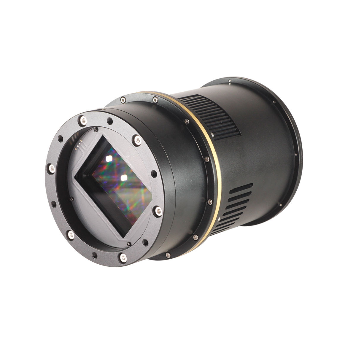
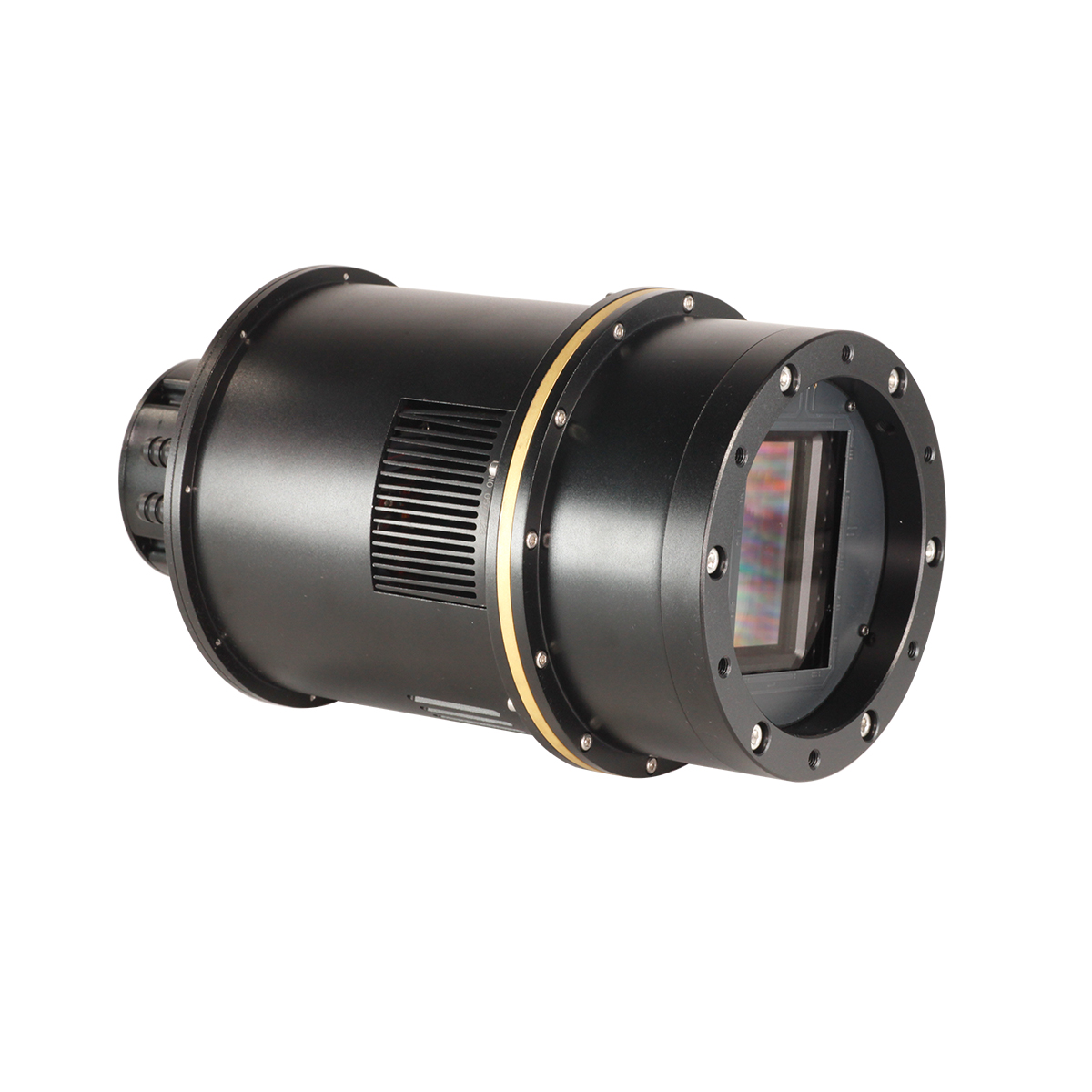
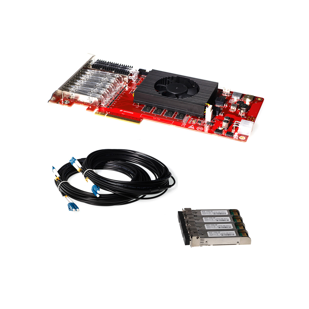
QHY411 Pro has 150 megapixels, with 54*40mm sensor size, while QHY461 Pro has 100 megapixels and 44*33mm sensor size. The features of their sensors are similar, back-illuminated, native 16bit A/D, medium format. Both QHY411 Pro and QHY461 Pro have 2*10GigaE interfaces and support higher readout speed. Mono and color version are both available. The applications include astronomy imaging, space object survey, satellite tracking, etc.
We offer the maxium flexibility to access all kinds of readout modes corresponding to different situations. Currently there is eight readout modes and will be more in the future.
Benefiting from its back-illuminated pixel structure, the QHY411 has a large full well of 80ke-. And when using 2 * 2 binning, the full well can reach 320ke-, corresponding to a merged pixel size of 7.5um * 7.5um. Combined with the low readout noise, the camera has a large dynamic range advantage.
Updated: now QHY411 supports 3*3 onchip binning. Learn more at “QHY411 3*3 Onchip Binning 12bit (high frame rate)Mode Instructions” part.
 Native 16 bit A/D: The new Sony sensor has native 16-bit A/D on-chip. The output is real 16-bits with 65536 levels. Compared to 12-bit and 14-bit A/D, a 16-bit A/D yields higher sample resolution and the system gain will be less than 1e-/ADU with no sample error noise and very low read noise.
 BSI: One benefit of the back-illuminated CMOS structure is improved full well capacity. In the back- illuminated sensor the light is allowed to enter the photosensitive surface from the reverse side. In this case the sensor’s embedded wiring structure is below the photosensitive layer. As a result, more incoming photons strike the photosensitive layer and more electrons are generated and captured in the pixel well. This ratio of photon to electron production is called quantum efficiency. The higher the quantum efficiency the more efficient the sensor is at converting photons to electrons and hence the more sensitive the sensor is to capturing an image of something dim.
 TRUE RAW Data: In the DSLR implementation there is a RAW image output, but typically it is not completely RAW. Some evidence of noise reduction and hot pixel removal is still visible on close inspection. This can have a negative effect on the image for astronomy such as the “star eater” effect. However, QHY Cameras offer TRUE RAW IMAGE OUTPUT and produces an image comprised of the original signal only, thereby maintaining the maximum flexibility for post-acquisition astronomical image processing programs and other scientific imaging applications.
 Zero Amplify Glow: This is also a zero amplifer glow camera.
 Cooling & Anti-dew Control: In addition to dual stage TE cooling, QHYCCD implements proprietary technology in hardware to control the dark current noise. The optic window has built-in dew heater and the chamber is protected from internal humidity condensation. An electric heating board for the chamber window can prevent the formation of dew.
 Sealing Technology: Based on almost 20-year cooled camera design experience, The QHY cooled camera has implemented the sealing control solutions. The sensor itself is kept dry with our silicon gel tube socket design for control of humidity within the sensor chamber. By the way, there’s no oil leaking.
Advanced Functions
Multiple Readout Modes
Multiple Readout Modes are special for QHY 16-bit Cameras (QHY600/268/461/411). Different readout modes have different driver timing, etc., and result in different performance. See details at “Multiple Readout Modes and Curves” Part.
Random change thermal noise suppression function
You may find some types of thermal noise can change with time in some back-illuminated CMOS cameras. This thermal noises has the characteristic of the fixed position of typical thermal noise, but the value is not related to the exposure time. Instead, each frame appears to have its own characteristics. The QHY600/268/461/411 use an innovative suppression technology that can significantly reduce the apparent level of such noise.
UVLO Protection
UVLO(Under Voltage Locking) is to protect the electronic device from damage caused by abnormally low voltages.
Our daily life experience tells us that the actual operational voltage of an electrical device must not significantly exceed the rated voltage, otherwise it will be damaged. For such precision equipment as cameras, long-term work at too low input voltage can also be detrimental to the working life of the camera, and may even make some devices, such as power manager, burn up due to long-term overload. In the all-in-one driver and SDK after 2021.10.23 stable version, the camera will give a warning when the input voltage of the camera is below 11V.
Optimizing USB Traffic to Minimize Horizontal Banding
It is common behavior for a CMOS sensor to contain some horizontal banding. Normally, random horizontal banding can be removed with multiple frame stacking so it does not affect the final image. However, periodic horizontal banding is not removed with stacking so it may appear in the final image. By adjust the USB traffic in Single Frame mode or Live Frame mode, you can adjust the frequency of the CMOS sensor driver and it can optimize the horizontal banding appeared on the image. This optimized is very effective to remove the periodic banding in some conditions.
A typical Periodic Horizontal Noise under certain USB_TRAFFIC values.
After Adjusting the USB Traffic to avoid the periodic horizontal noise.
Reboot the camera by power off and on
The camera is designed to use the +12V to reboot the camera without disconnecting and reconnecting the USB interface. This means that you can reboot the camera simply by shutting down the +12V and then powering it back on. This feature is very handy for remote controlling the camera in an observatory. You can use a remotely controlled power supply to reboot the camera. There is no need to consider how to reconnect the USB in the case of remote control.
QHY411 3*3 Onchip Binning 12bit (high frame rate)Mode Instructions
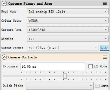
Now QHY411 supports onchip 3 * 3 binning. Compared with software binning of most software binning, onchip (hardware) binning can reach higher frame rates.
Since most software that provides continuous mode/video output, like SharpCap, only support 8-bit or 16-bit oupout, so you must select 8-bit output to achieve a frame rate boost.
Data comparison (USB3.0 full resolution)
1*1 bin: 8-bit, 2fps
3*3 Onchip Binning 12bit Mode: max 20fps
![]()
To get the update, you need the latest firmware and All-in-one Driver Pack.
Allinone Update: please refer to the description on the “Download” page of the website.
Firmware Update: Requires downloading firmware update kit 20220824 or later. If you have an old firmware upgrade tool locally, please discard it. The compressed package contains firmware upgrade tools, new QHY411 firmware and upgrade operation instructions. Please read the upgrade instructions in the firmware installation package carefully. If you encounter any problems during the upgrade, please contact us.
Firmware upgrade kit 20220824 download address:
Firmware upgrade instructions:
Refer to the compressed document or web version instructions
Specifications
| Model | QHY411 Pro | QHY461 Pro |
| Image Sensor | Sony IMX411 | Sony IMX461 |
| Sensor Type | Both Available | Both Available |
| FSI/BSI | BSI | BSI |
| Pixel Size | 3.76μm*3.76μm | 3.76μm*3.76μm |
| Effective Pixels | 151 Megapixels | 102 Megapixels |
| Effective Image Area | Typical 4.2inch (54mm*40mm) | Typical 3.4inch (44mm*33mm) |
| Effective Pixel Area | 14208*10656 | 11664*8748 |
| Total Pixel | 14304*10748 (include optical black area and overscan area) | 11760*8842 (include optical black area and overscan area) |
| A/D | Native 16-bit (0-65535 greyscale) A/D | Native 16-bit (0-65535 greyscale) A/D |
| Full Well Capacity (1×1, 2×2, 3×3)
|
Standard Mode
50ke- / 200ke- / 450ke- Extended Fullwell Mode 80ke- / 320ke- / 720ke- |
Standard Mode
50ke- / 200ke- / 450ke- Extended Fullwell Mode 80ke- / 320ke- / 720ke- |
| Read Noise | 1e- to 3e- (HGC Mode) | 1e- to 3e- (HGC Mode) |
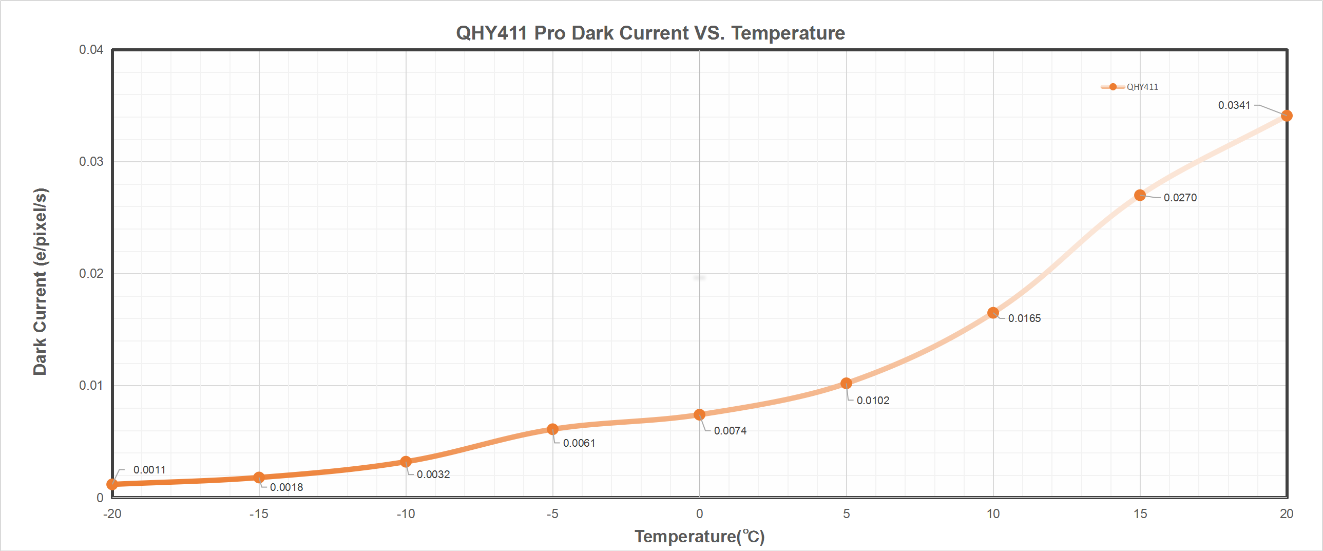
| Dark Current | Apporx 0.0011e-/pixel/sec @-20℃ | Approx 0.003e-/pixel/sec @-20℃ |
| Exposure Time Range | 20μs – 3600sec | 50μs – 3600sec |
| Shutter Type | Electronic Rolling Shutter | Electronic Rolling Shutter |
| Computer Interface | USB3.0
2*10Gigabit Fiber |
USB3.0
2*10Gigabit Fiber |
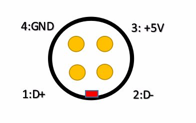
| Filter Wheel Interface
|
4PIN QHYCCD CFW Port | 4PIN QHYCCD CFW Port |
| Trigger Port | Programmable TrigOut, High Speed Sync Port / GPS interface Port | Programmable TrigOut, High Speed Sync Port / GPS interface Port |
| Full Frame Rates | USB3.0:
2.1FPS@8bit 1.0FPS@16bit
PCIE Mode: 2.1FPS@8bit 2.1FPS@16bit |
USB3.0:
2.7FPS@8bit 1.7FPS@16bit
PCIE Mode: 3.0FPS@8bit 2.0FPS@16bit |
| ROI Frame Rates
|
USB3.0:
2048lines, 10.2FPS@8bit, 5.1FPS@16bit 1080lines, 18.5FPS@8bit, 9.8FPS@16bit 768lines, 25.3FPS@8bit, 12.9FPS@16bit 480lines, 36.6FPS@8bit, 19.2FPS@16bit
3×3 Onchip Binning 12bit: 3548lines, 20.2FPS@8bit, 10.1FPS@16bit 1080lines, 62.6FPS@8bit, 32.8FPS@16bit 768lines, 84.8FPS@8bit, 43.2FPS@16bit 480lines, 131FPS@8bit, 68.8FPS@16bit
PCIE Mode: 2048lines, 10.2FPS@8bit, 5.1FPS@16bit 1080lines, 18.5FPS@8bit, 9.8FPS@16bit 768lines, 25.3FPS@8bit, 12.9FPS@16bit 480lines, 36.6FPS@8bit, 19.2FPS@16bit
PCIE 3×3 Onchip Binning 12bit: 3548lines, 20.2FPS@8bit, 12.6FPS@16bit 1080lines, 62.6FPS@8bit, 43.6FPS@16bit 768lines, 84.8FPS@8bit, 43.2FPS@16bit 480lines, 131FPS@8bit, 102FPS@16bit |
USB3.0:
2048lines, 10.8FPS@8bit, 6.1FPS@16bit 1080lines, 19.5FPS@8bit, 10.8FPS@16bit 768lines, 26.1FPS@8bit, 14.7FPS@16bit 480lines, 37.1FPS@8bit, 20.5FPS@16bit
PCIE Mode: 2048lines, 10.9FPS@8bit, 9.2FPS@16bit 1080lines, 19.7FPS@8bit, 18.6FPS@16bit 768lines, 25.8FPS@8bit, 24.6FPS@16bit 480lines, 36.6FPS@8bit, 35.5FPS@16bit |
| Built-in Image Buffer | 2GB DDR3 Memory Buffer | 2GB DDR3 Memory Buffer |
| Air Cooling System | Dual Stage TEC cooler:
– Long exposures (> 1 second) Typically -35℃ below ambient – Short exposure (< 1second) high FPS, Typically -30℃ below ambient(Test temperature +20℃) |
Dual Stage TEC cooler:
– Long exposures (> 1 second) Typically -35℃ below ambient – Short exposure (< 1second) high FPS, Typically -30℃ below ambient(Test temperature +20℃) |
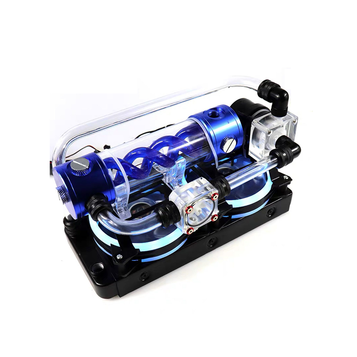
| Liquid Cooling | Available.
-45℃ below ambient with water cooling; more deltaT below ambient with cold liquid. |
Available.
-45℃ below ambient with water cooling; more deltaT below ambient with cold liquid. |
| Recommended Flow Rates | 12ml/s | 12ml/s |
| Anti-Dew Heater | Available | Available |
| Humidity Sensor | Available | Available |
| Firmware/FPGA remote Upgrade | Available via Camera USB port | Available via Camera USB port
|
| Optic Window Type | AR+AR High Quality Multi-Layer Anti-Reflection Coating | AR+AR High Quality Multi-Layer Anti-Reflection Coating |
| Back Focal Length | 16mm(without tilt adjust ring)
28.5mm (with tilt adjust ring) |
16mm (without tilt adjust ring)
28.5mm (with tilt adjust ring) |
| Adapters | Customization | Customization |
| Weight | 2.9kg | 2.9kg |
| Power | 49.2W/100%
28.9W/50% 17.3W/0% |
49.2W/100%
28.8W/50% 16.8W/0% |
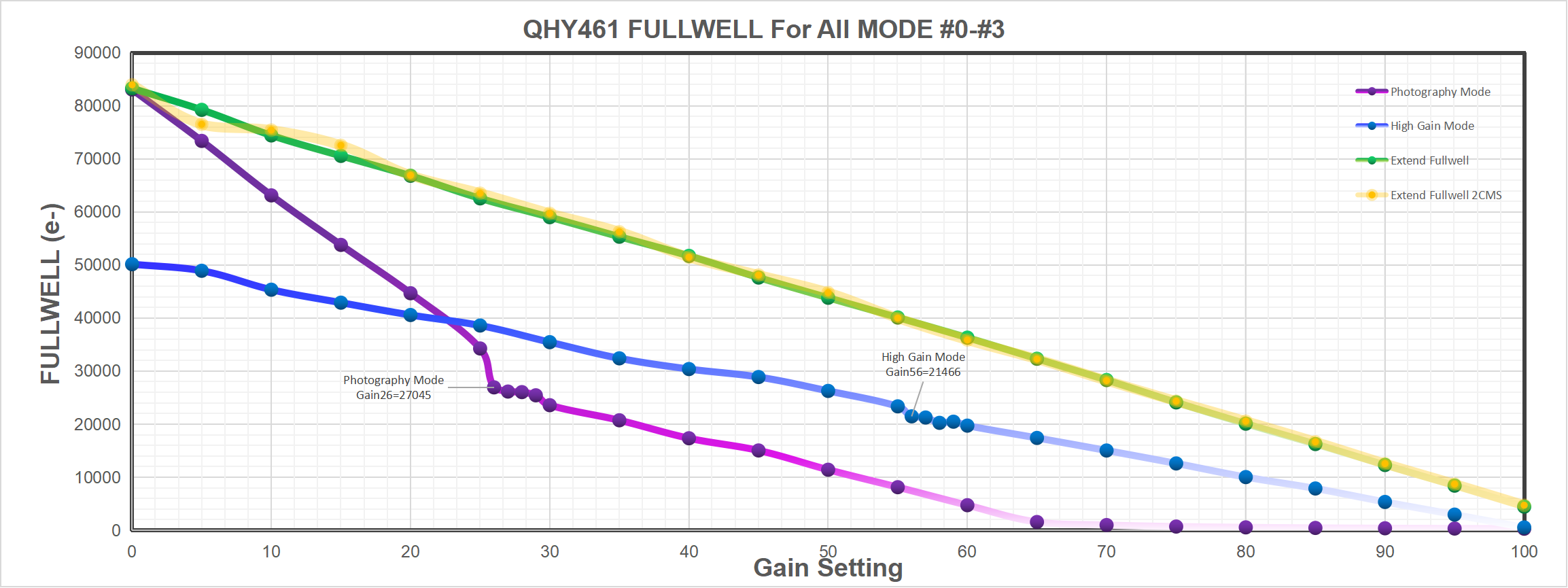
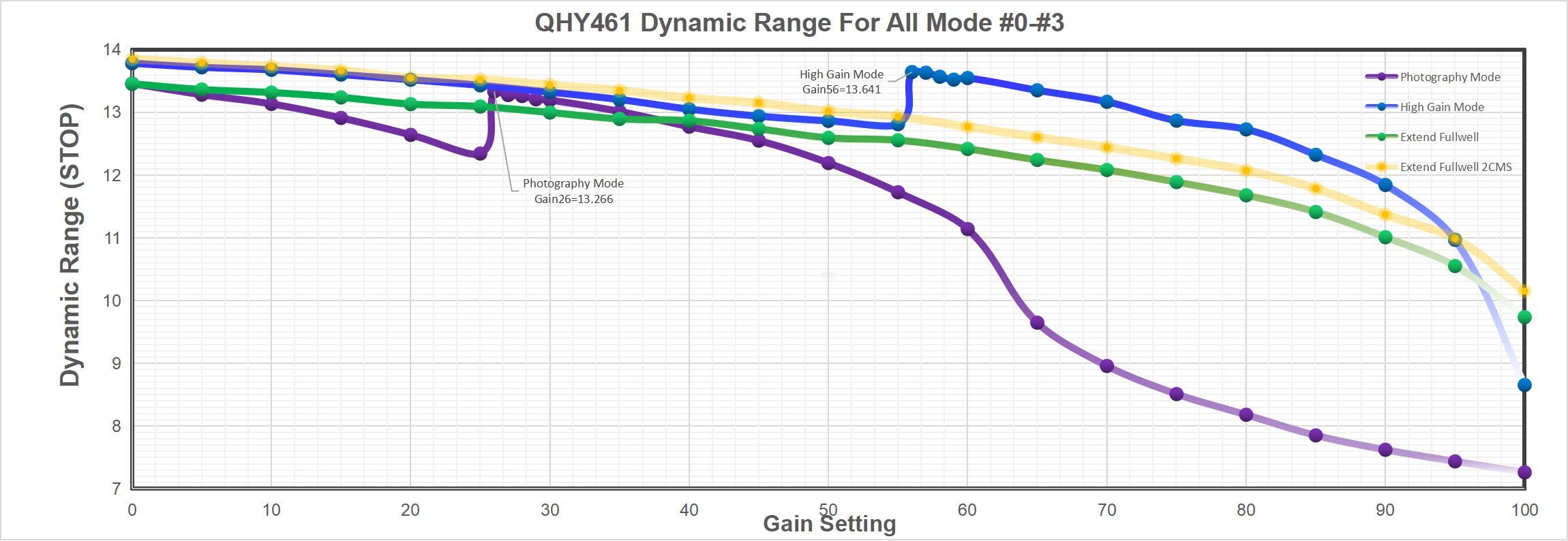
QHY411 Pro Curves
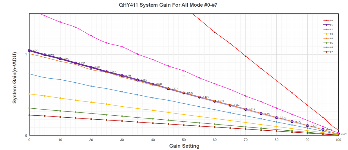
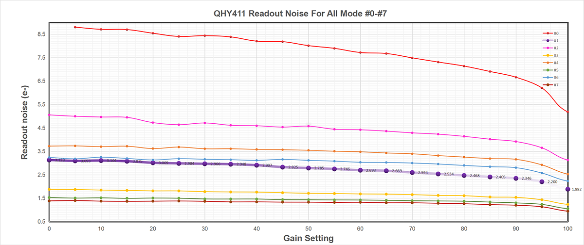
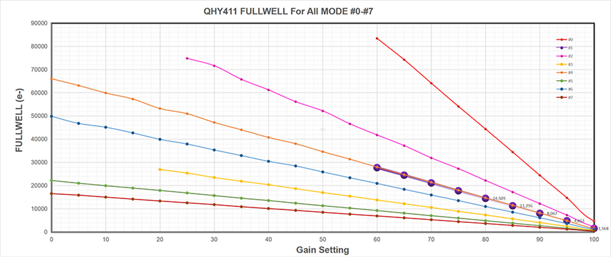
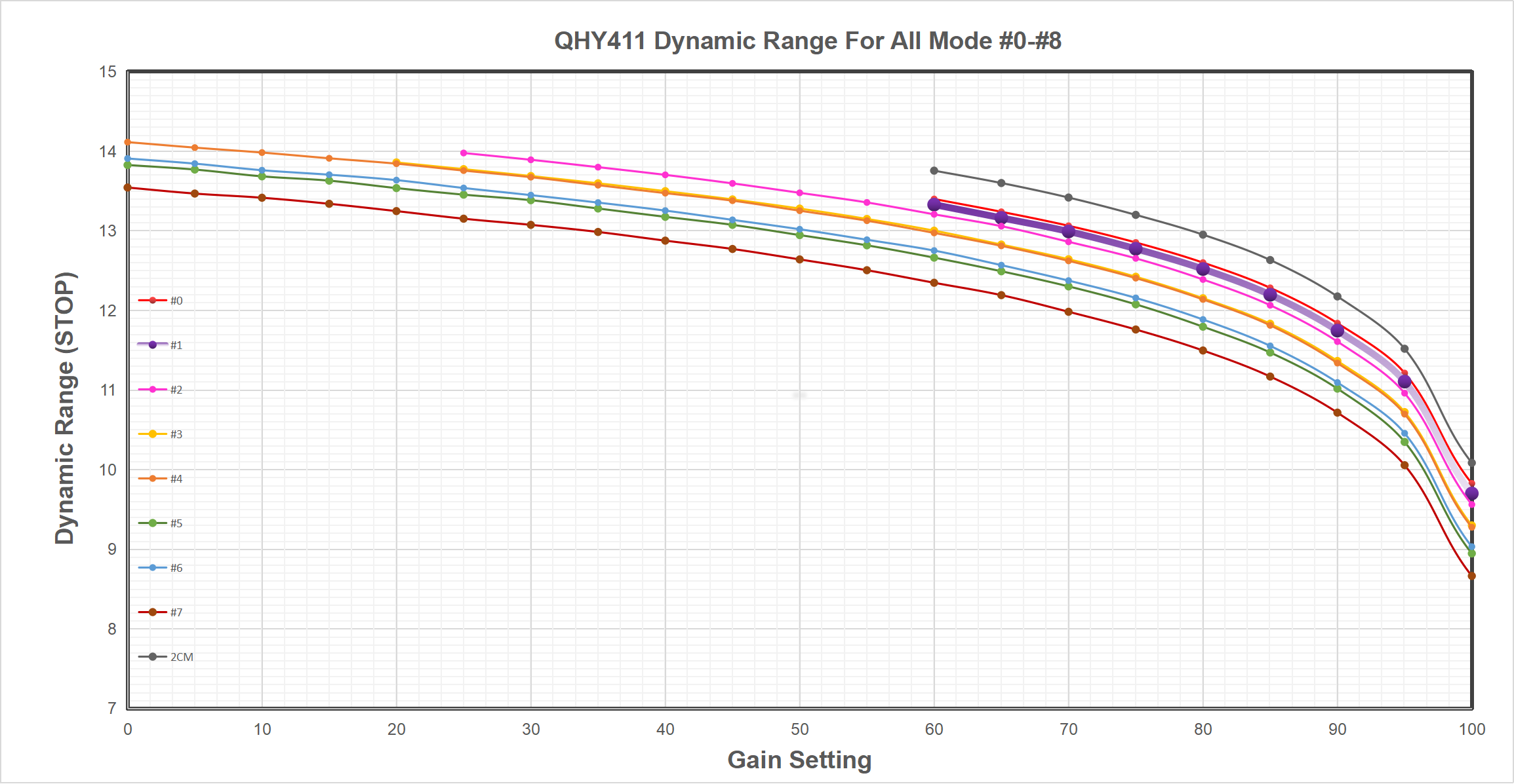
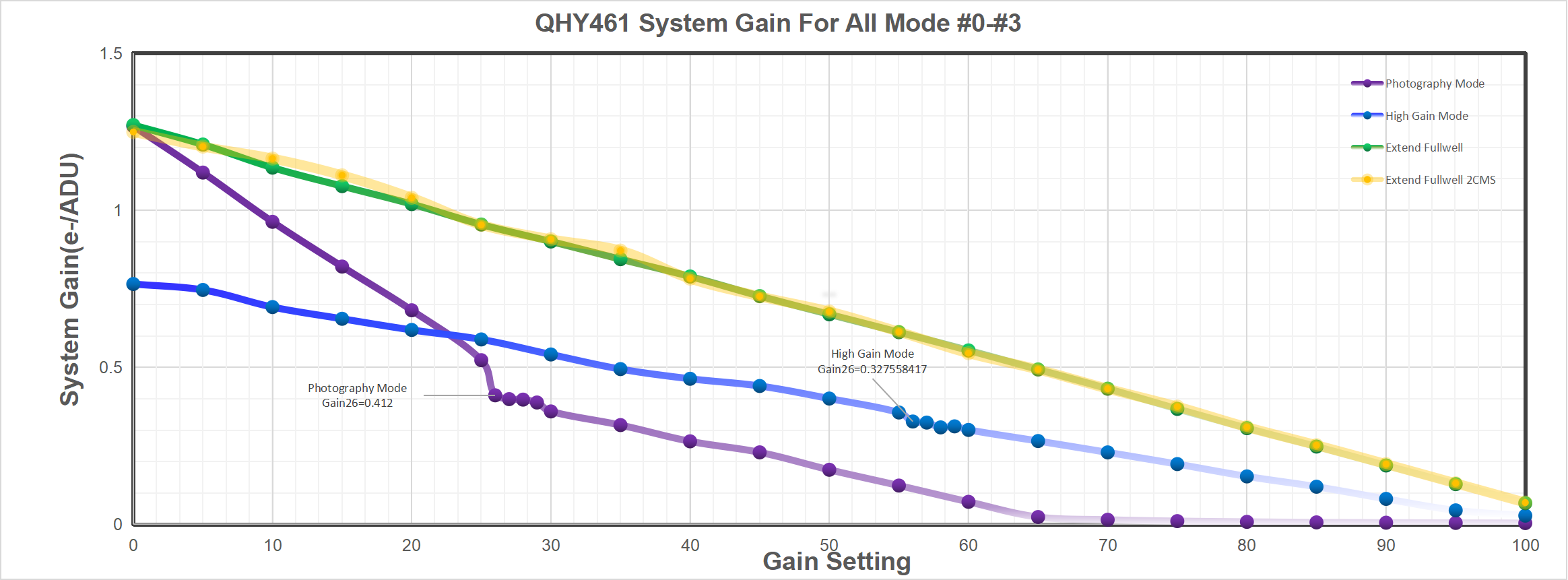
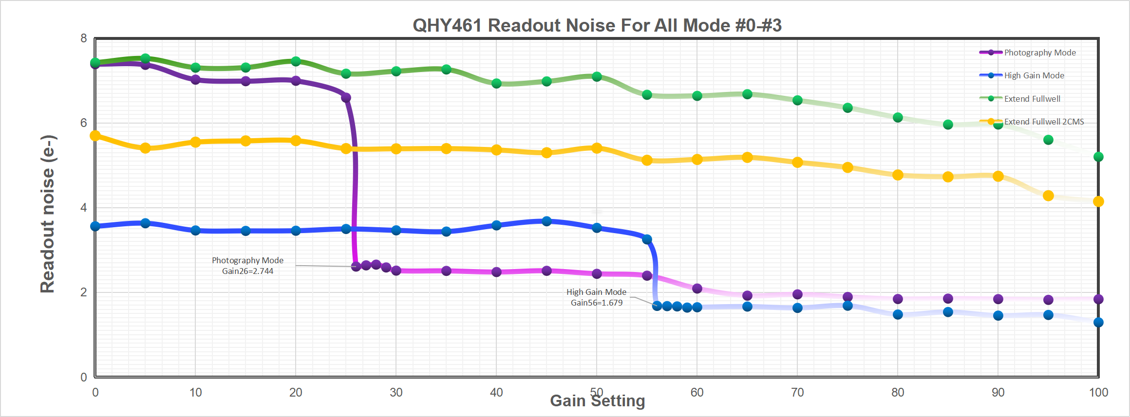
We offer the maxium flexibility to access all kinds of readout modes corresponding to different situations. Currently there is eight readout modes and will be more in the future.
The eight readout modes is mode #0 to mode #7. The follwing graph is the system gain, readout noise and fullwell of each mode. Different mode has different behaviour in both fullwell, readout noise , and some other noise conditions. You can select the suitable mode according the applications. You can also download the detailed messured data from this link (excel file) QHY411_CURVES_ALLMODE – Download
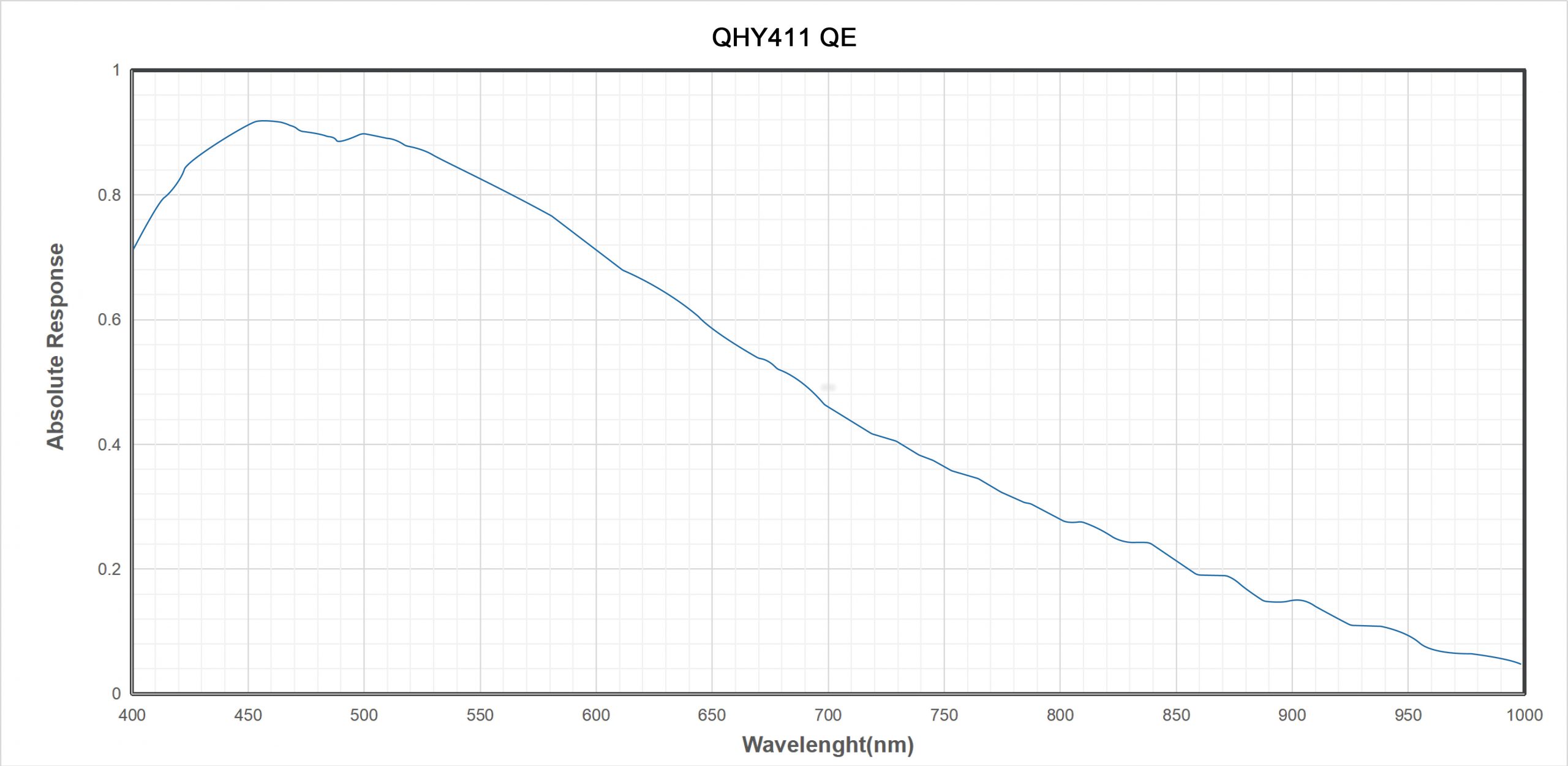
QHY411 QE. Since SONY has not release the absolutely QE curve of IMX411. There is only the relativity QE Curve. QHYCCD did some test of absolutely QE for the 3.76um BSI sensor in another model. It can be used for just a reference. This article can be found in https://www.qhyccd.com/index.php?m=content&c=index&a=show&catid=23&id=261
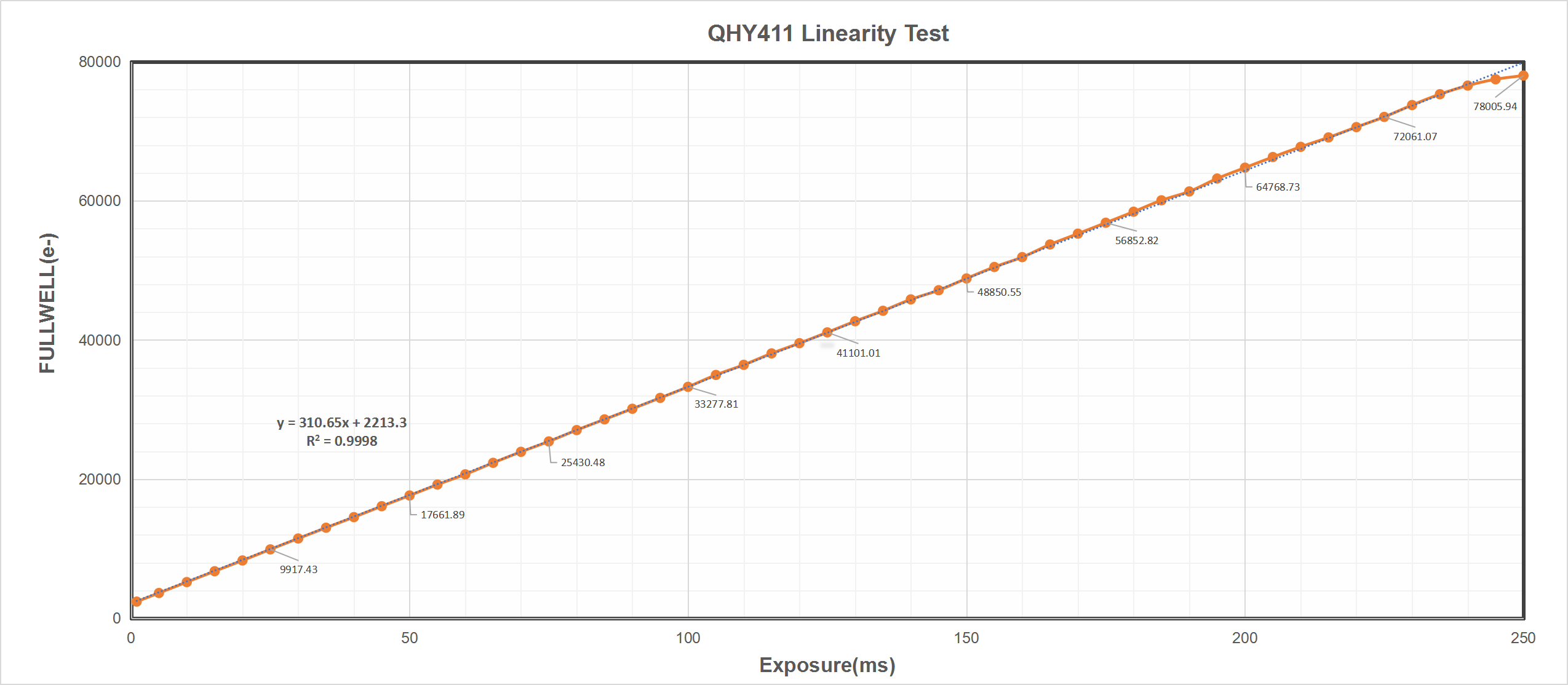
Regarding the linearity of QHY411, we conducted a preliminary linearity determination experiment. QHY411 data can be used to enable astronomical metering.
The experiment is to obtain a deviation of a fixed area by shooting the flat field plate with different exposure times. Then, after converting the conversion to a value in units of volume, the curve where the overlapping exposure time is increased and replaced by the image sensor is replaced.
In order to obtain relatively large full-scale range data. We used the QHY411 correction mode with a gain of 0 (GAIN = 60). The obtained curve is as follows. You can see from the picture. QHY411 has very good linearity in a wide range. When the full scale is greater than 75000e, the linearity begins to decrease, and the curve conforms to the general linearity of the image sensor in the near area.
QHY461 Pro Curves
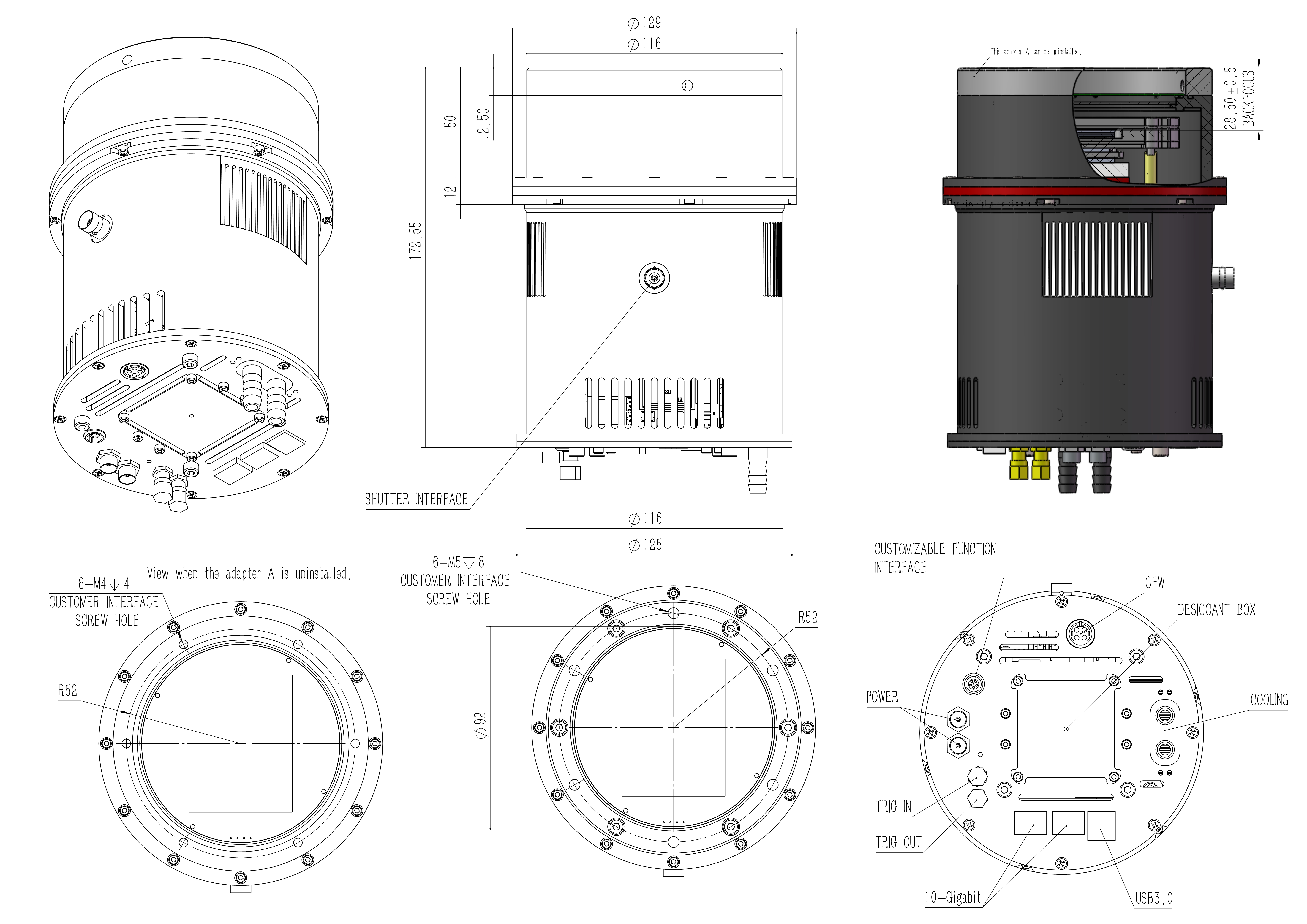
Mechanical Dimentions
Sample Images
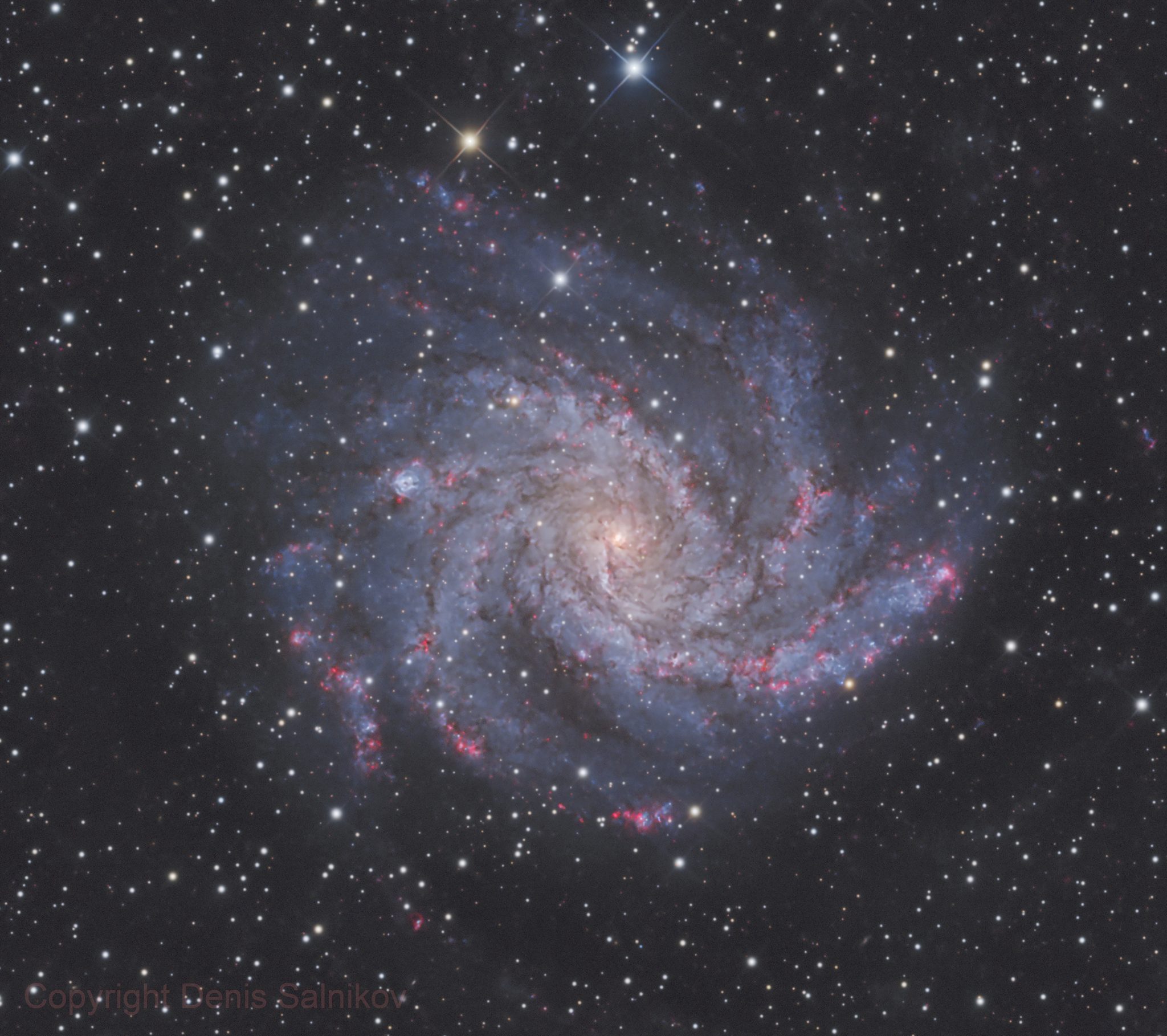
Fireworks Galaxy
Image credit and copyright: Denis Salnikov
https://www.astrobin.com/4arko5/
Telescope: AG Optical iDK 14.5 inch F6.7
Camera: QHY461
Mount: Paramount Taurus 400
Filters: Astrodon Gen2 E-Series Tru-Balance Blue 50×50 mm · Astrodon Gen2 E-Series Tru-Balance Green 50×50 mm · Astrodon Gen2 E-Series Tru-Balance Lum 50×50 mm · Astrodon Gen2 E-Series Tru-Balance Red 50×50 mm · Astrodon H-alpha 3nm 50×50 mm
Integration: 118h 53′ 20″
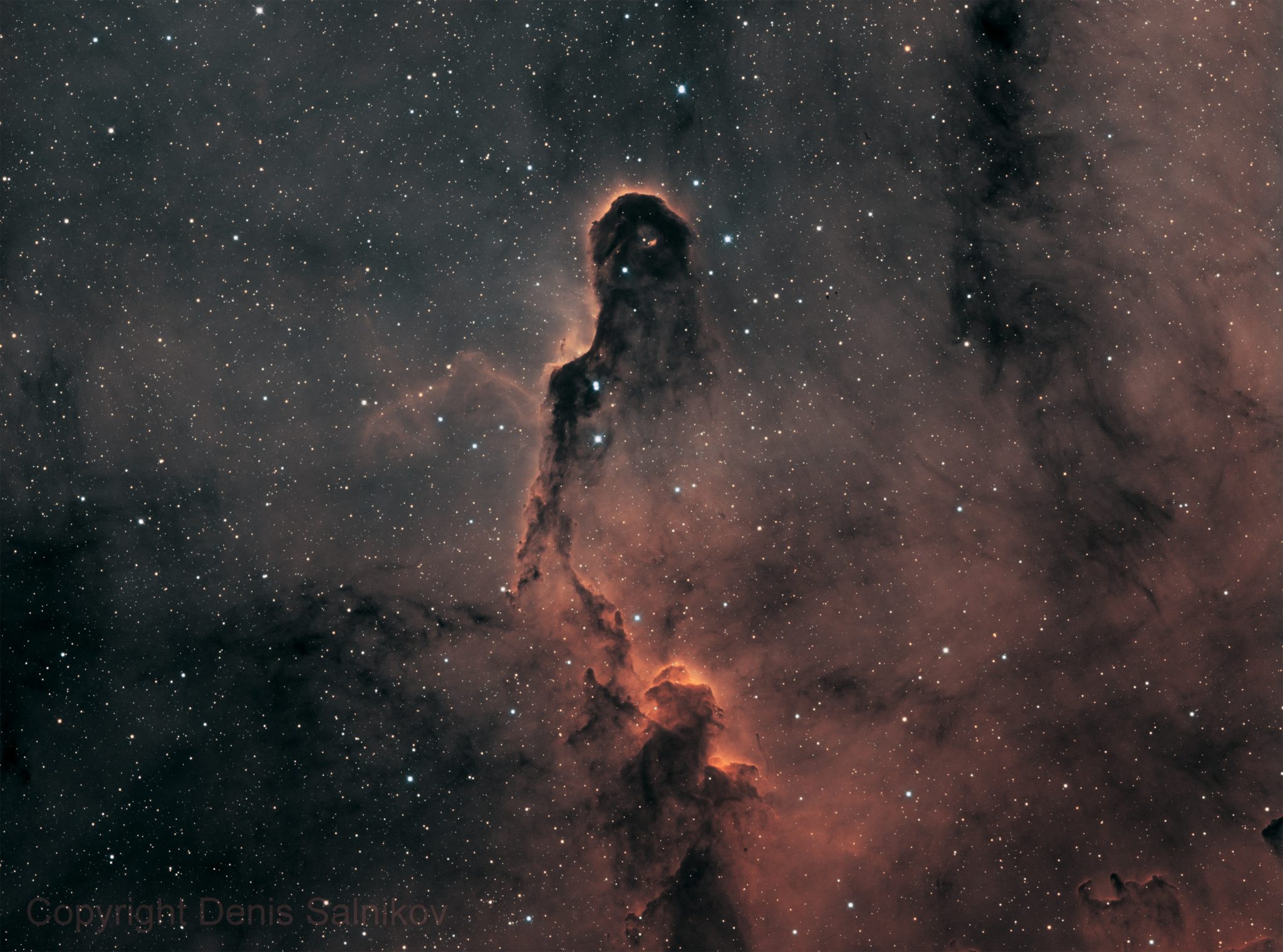
IC 1396 Elephant’s Trunk Nebula in Bi-Color palette
Image credit and copyright: Denis Salnikov
https://www.astrobin.com/x51ogf/0/
Telescope: AG Optical iDK 14.5 inch F6.7
Camera: QHY461
Mount: Paramount Taurus 400
Filters: Astrodon OIII 3nm 50mm · Astrodon Ha 3nm 50mm
Integration: 12h 30′
Reference Paper / Document
Some scholars in Italy found secrets hidden in ancient manuscripts with the QHY411 camera.
StarDICE I: sensor calibration bench and absolute photometric calibration of a Sony IMX411 sensor, a paper about QHY411 camera was published in the Astronomy & Astrophysics.
https://arxiv.org/pdf/2211.04913.pdf
A new paper named Scientific CMOS Sensors in Astronomy: QHY600 and QHY411 has been published! It was finished by researchers from the Institute of Astrophysics of Canarias (IAC), Spain.
https://arxiv.org/abs/2302.03700
A new paper A Shock Flash Breaking out of a Dusty Red Supergiant by researchers from Tsinghua University, PMO, Tel Aviv University, NAOC, and UC Berkeley has been published in Nature. An Antarctic Survey Telescope (AST3)-3 equipped with a QHY411 camera at the Yaoan station of Purple Mountain Observatory, China was involved in this observation and provided important data.
https://www.nature.com/articles/s41586-023-06843-6
https://arxiv.org/abs/2311.14409
Basic Uesr Menu
Install “All-In-One” Driver&SDK Pack
Before Start: Input Voltage Requirements
The camera requires an input voltage between 11V and 13.8V. If the input voltage is too low the camera will stop functioning or it may reboot when the TEC power percent is high, causing a drain on the power. Therefore, please make sure the input voltage arrived to the camera is adequate. 12V is the best but please note that a 12V cable that is very long or a cable with small conductor wire may exhibit enough resistance to cause a voltage drop between the power supply and the camera. The formular is: V(drop) = I * R (cable). It is advised that a very long 12V power cable not be used. It is better to place the 12V AC adapter closer to the camera.
First connect the 12V power supply, then connect the camera to your computer via the USB3.0 cable. Make sure the camera is plugged in before connecting the camera to the computer, otherwise the camera will not be recognized. When you connect the camera for the first time, the system discovers the new device and looks for drivers for it. You can skip the online search step by clicking “Skip obtaining the driver software from Windows Update” and the computer will automatically find the driver locally and install it. If we take the 5IIISeries driver as an example (shown below), after the driver software is successfully installed, you will see QHY5IIISeries_IO in the device manager.
Please note that the input voltage cannot be lower than 11.5v, otherwise the device will be unable to work normally.
Install "All-In-One" System Pack
All-in-one Pack supports most QHYCCD models only except PoleMaster and several discontinued CCD cameras.
Download Page: https://www.qhyccd.com/download/
Video Tutorial: https://www.youtube.com/embed/mZDxIK0GZRc?start=1
- Since most of the contents of All-in-one package are plug-ins that support third-party software, the third-party capturing software that you want to use must be installed before the All-in-one package. Otherwise the program will report an error.
- ALL-IN-ONE Pack contains:
- System Driver, which is necessary for the camera operation and must be installed.
- WDM Broadcast Driver, which can provide a live signal to Obs and other live software, you can install it if you have such needs like opeing a live show.
- EZCAP_QT , which is developed by QHYCCD and can be used in QHY devices tests, and management of updates. So even if you won’t use EZCAP_QT for capturing, we suggest you install it.
- Ascom driver, which is necessary for the camera used in Ascom (the latest version of Ascom is 6.6).
- The two sorts of Ascom CFW Drivers correspond to two methods of controling the filter wheel: USB control and camera serial control. It is recommended that both drivers should be installed if you have a filter wheel.
- CP210X_VCP is a serial driver. Some computers come with the driver, but the computer without the driver may be failed of controling the filter wheel.
- SDKs for Third-party Software: Just pick and install the corresponding SDK according to the software you want to use. Don’t forget to check whether the software you are using is 32-bit or 64-bit and select the right SDKs.
- SHARPCAP is also included in the pack, you can choose 32-bit or 64-bit to install. This is authorized by SHARPCAP.
- QT LIB is a plug-in to ensure that 64-bit software can exeuate normally on some computers with poor compatibility.
- Difference between Stable version and Beta Version: Beta version is the latest version, which gives priority to support for the latest products (the stable version may not be compatible with those yet), and has some of the latest optimized ,but experimental features. The stable version is older than the beta version but more stable, so it is recommended for beginners who are not using the latest products.
- Don’t let the camera connect to the computer during the All-in-one pack installation process; connect it to the computer after all the installation is complete.
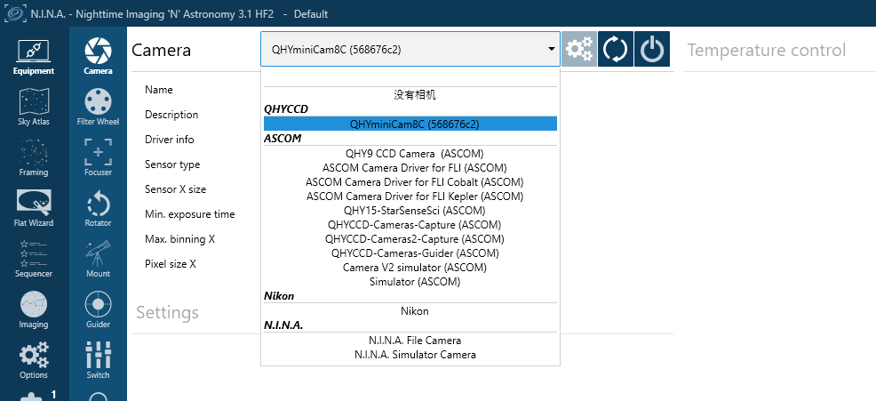
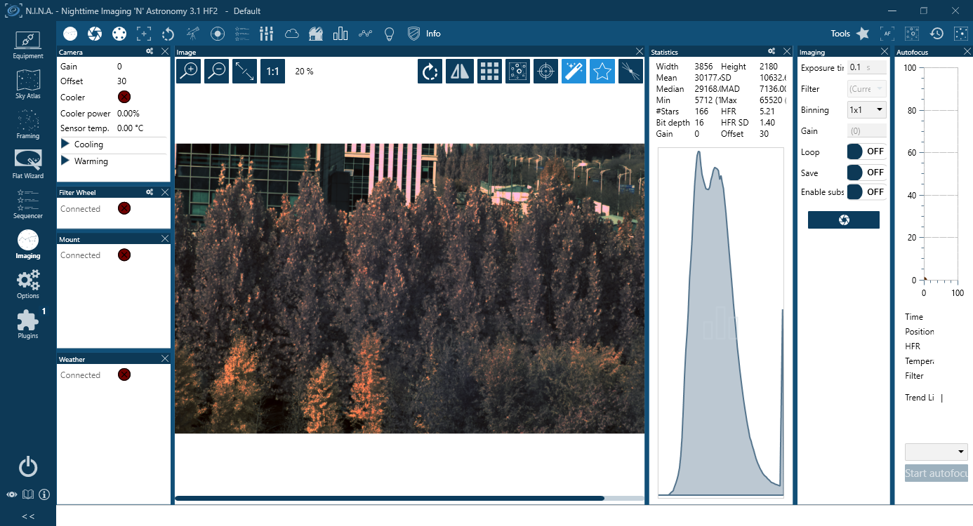
Connect DSO Imaging Software (e.g. NINA)
Before using software, make sure you have connected the cooling camera to the 12V power supply and connected it to the computer with a USB3.0 data cable. If it’s an uncooled camera, 12V power is not needed. We recommend 64-bit Software, like SharpCAP x64 , N.I.N.A x64. etc., especially when you’re using 16bit cameras.
NINA supports direct connection via the QHY plugin as well as connection through the ASCOM driver. The following instructions assume a direct connection using the QHY plugin.
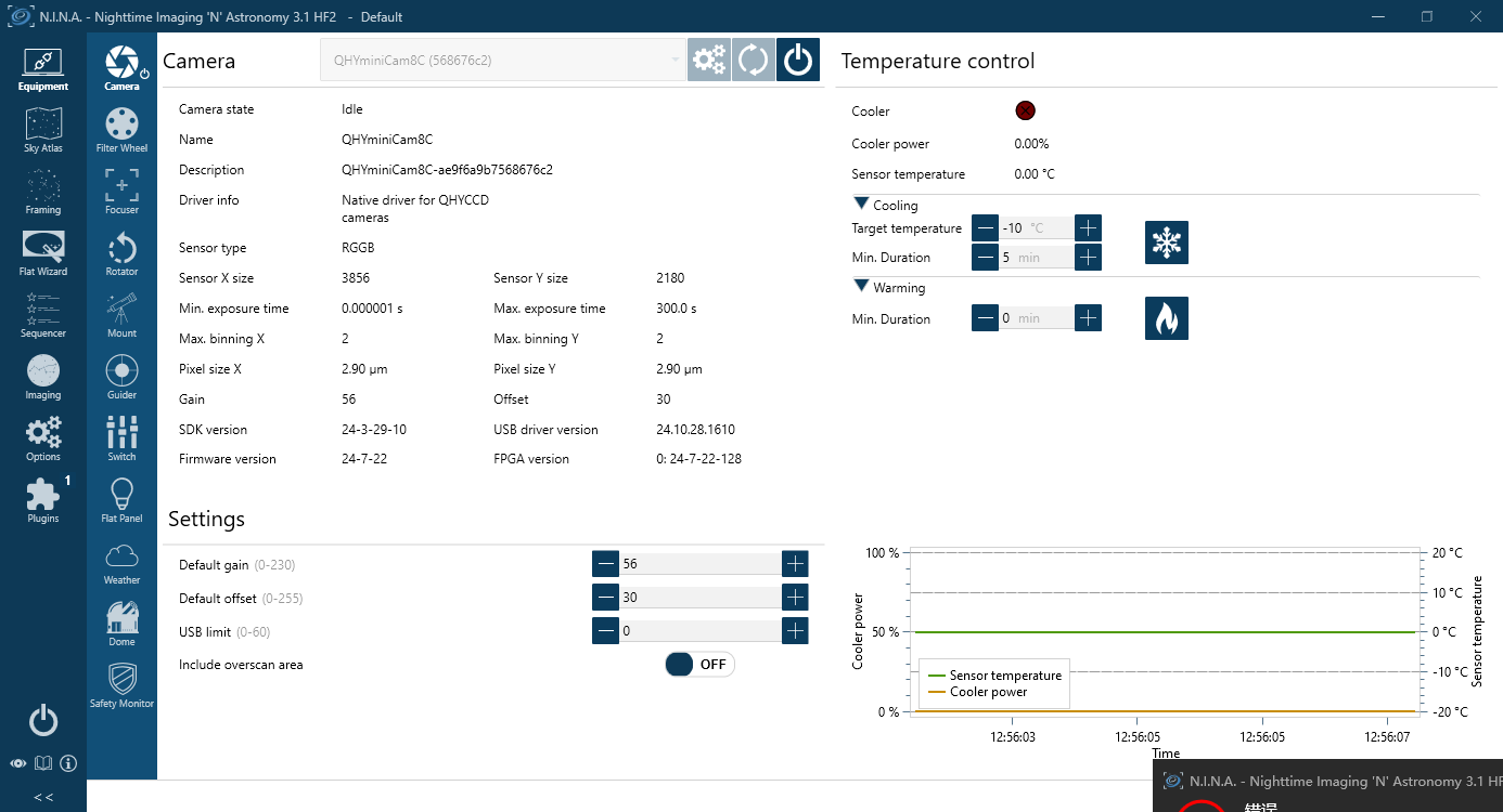
Set the Target temperature.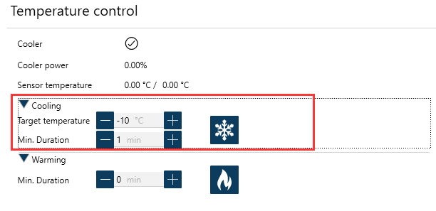
Set exposure time and start the shooting.
Connect Planetary Imaging Software (e.g. SharpCap)
The instructions below are based on SharpCap 3.1
- Launch SharpCap.
Click Camera in the menu bar and select your camera.
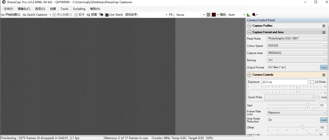
If the software and drivers mentioned above have been installed correctly, the image will appear automatically. And the frame rate can also be seen in the lower-left corner of the software window, as shown below.
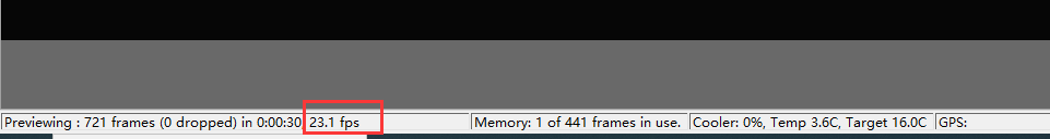
- Main Interface Functions:
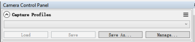
Capture Profiles
Preset management.
After SharpCap is restarted, the default settings are restored. If you frequently use one or more specific parameter configurations, you can adjust the parameters as needed and then click Save to store them as a preset. The preset can be directly recalled the next time you open the software.
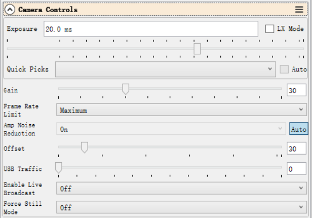
Exposure
Sets the exposure duration. When LX Mode is enabled, the single-frame exposure time can be extended to longer values.
Gain
Equivalent to the ISO setting on a standard digital camera. Higher gain values result in higher sensitivity.
Frame Rate Limit
Limits the maximum frame rate. By default, no limit is applied. Users can set the limit manually if needed.
Offset
Adjusts the bias level. Even when the camera is completely covered, the image may not appear perfectly black. By adjusting the offset value, a more optimal dark frame can be achieved. The Histogram can be used to verify the adjustment.
USB Traffic
Controls the data transfer speed (frame rate). When set to 0, the camera operates at its maximum frame rate.
Enable Broadcast Mode
Enables the broadcast driver. For detailed usage instructions, please refer to the documentation available on the download page.
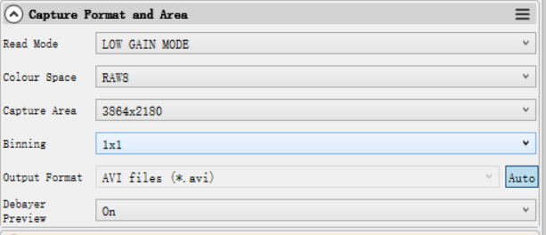
Read Mode
Some camera models support high-gain and low-gain readout modes.
Color Space
Select the output format.
Raw8 / Raw16 are 8-bit or 16-bit formats. Images and videos saved in Raw8 or Raw16 format will be monochrome, even when using a color sensor. Color information must be restored through debayering during post-processing.
RGB24 is a non-RAW format that outputs color images directly, but requires more storage space.
Capture Area
Select the resolution used for image capture.
Binning
Enable pixel binning for image capture.
Output Format
Select the output file format.
Debayer Preview
When this function is enabled, the live preview will be displayed in color even if a RAW format is selected. Please note that the saved images will still be monochrome.
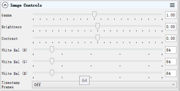
Gamma, Brightness, Contrast
Under normal operating conditions, we recommend leaving these settings unchanged.
White Balance (R/G/B)
This function is used for white balance calibration on color cameras. For detailed calibration instructions, please refer to the corresponding section on the color camera page.
This function is not required for monochrome cameras.
Histogram
The histogram is an important image reference tool. It can be used to check whether the white balance is set correctly, whether the offset value is appropriate, and whether the image is overexposed.
Its operating principle is the same as that of the histogram used in standard DSLR cameras.

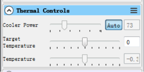
Thermal Controls
After the cooled camera is connected to a 12 V power supply, the temperature control circuit will be activated. You can control the CMOS sensor temperature by adjusting the settings shown below.
There are two main methods for temperature control:
Adjusting the cooler power
Setting a target temperature
If you wish to control the CMOS temperature by setting a target temperature, first click “Auto”, and then use the slider to set the desired target temperature.
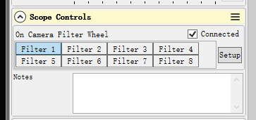
Scope Control: for filter wheel control
Select the corresponding filter wheel slot to control the rotation.
Note: The software must be started after the filter wheel has completed its rotation and returned to the home position; otherwise, the position will not be displayed correctly.
Using Ascom
QHY devices can operate with many software applications that support the ASCOM platform. MAXIM DL is used as an example below.
First, make sure that both the ASCOM platform and the QHY ASCOM driver have been successfully installed. Launch MAXIM DL and follow the instructions shown in the figure below to complete the setup.
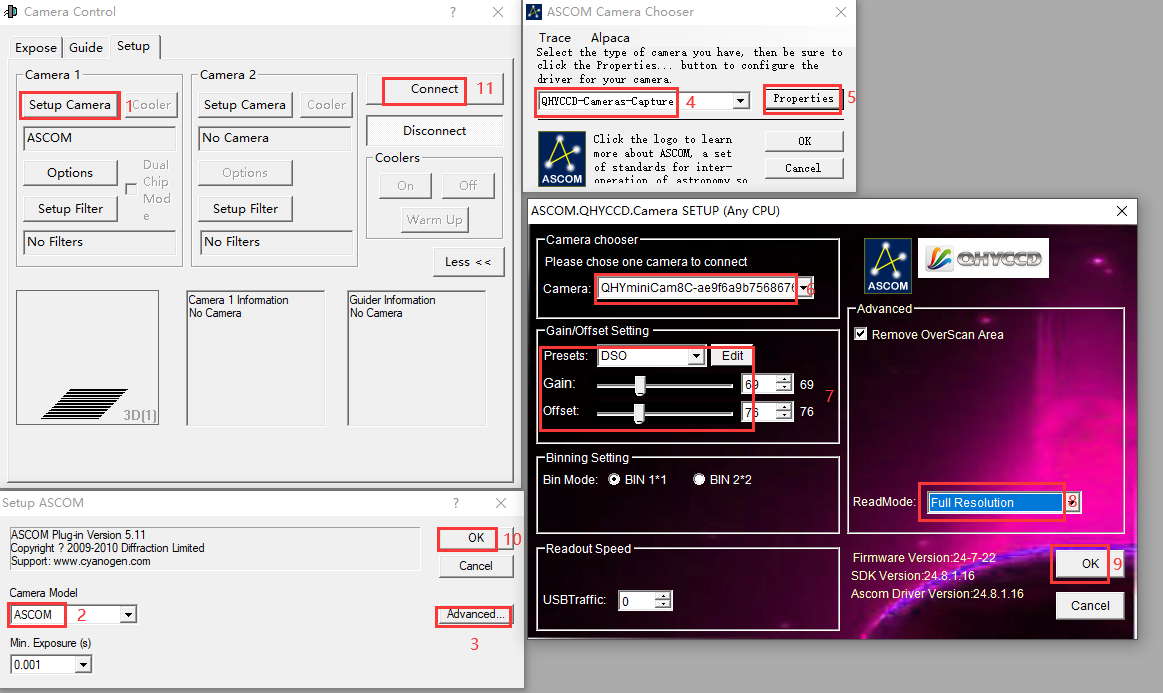
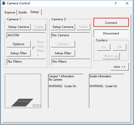
Click “Connect”
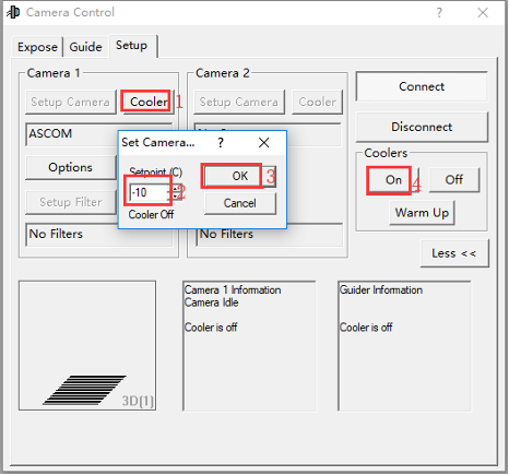
Set the cooling temperature.
Using EZCAP
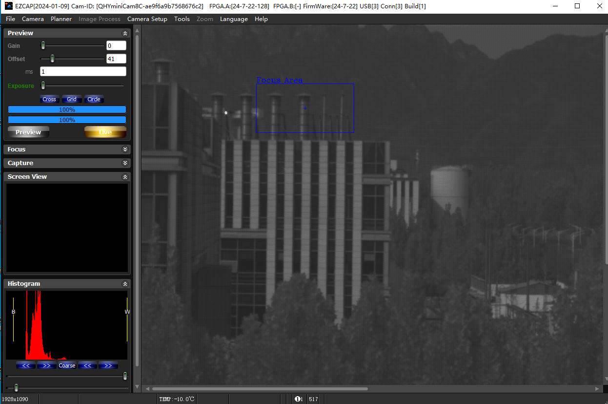
EZCAP_QT is software developed by QHYCCD. For QHYCCD cameras, it provides basic image capture functions.
Install the EZCAP_QT software and connect the camera to your computer using a USB 3.0 cable. Launch EZCAP_QT, then click “Connect” under Menu → Camera.
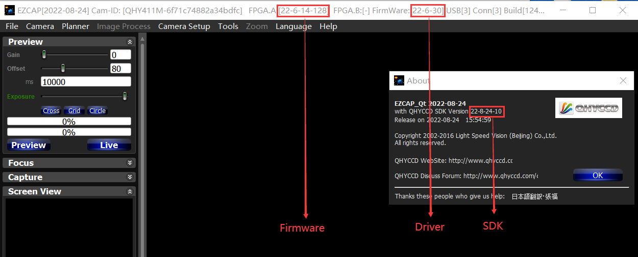
If the camera is successfully connected, the EZCAP_QT title bar will display the camera firmware version and camera ID, as shown in the figure below.

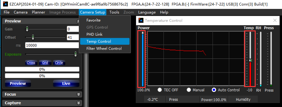
In Camera Setup, click Temp Control to set the CMOS sensor temperature.
You can enable Auto to define a target temperature. For example, here we set the target temperature to –10 °C. The CMOS sensor temperature will quickly drop to the target value, typically within 2–3 minutes.
To disable cooling, select Stop. If you prefer to control the cooling power without setting a target temperature, you can manually set the cooling power as a percentage.
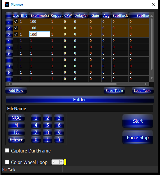
In EZCAP_QT, there is an Image Task Planner for sequence imaging.
Check Use to enable the task.
Set the following parameters:
Bin
ExpTime – exposure time
Repeat – number of frames
CFW – filter wheel position
Gain – gain value for the sequence
Click Folder to set the save path. (It is recommended to avoid special characters in the path and use English letters.)
Click Start to begin the sequence capture, and Force Stop to close the current task.
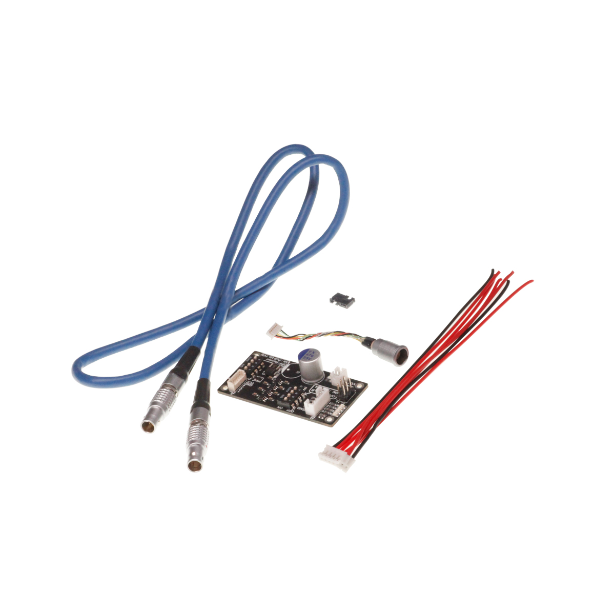
Advanced Control Tools
Click to download (2021.1.2)
Run Sharpcap and make sure the QHY Camera works well under it. You will see the continous image appears.
Click “connect” button and it will show camera name and series number.
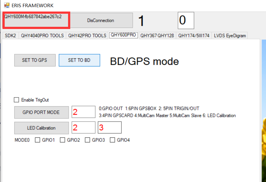
select QHY Camera tabl.
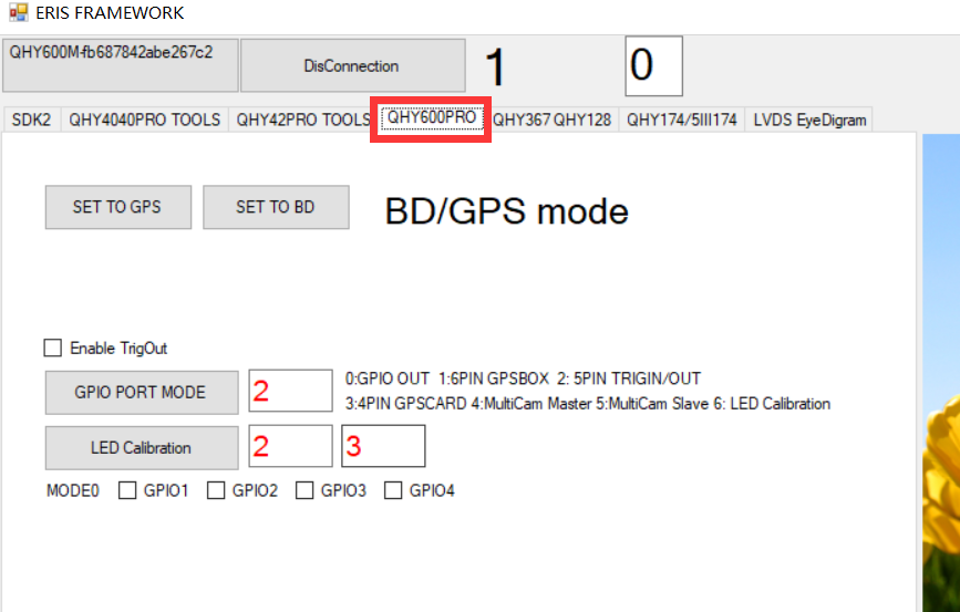
check on the “Enable TrigOut” Input 2 to the textbox near to the “GPIO PORT MODE”. Then click the “GPIO PORT MODE” Button to set the GPIO working mode.
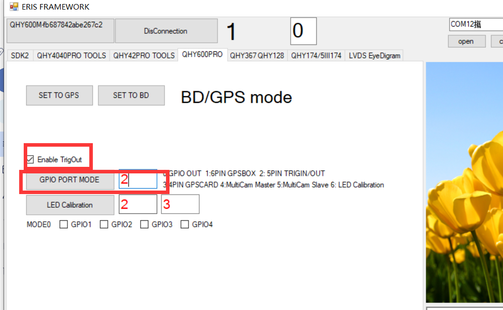
Check the waveform output from the TrigPort.
The introduction of different GPIO PORT MODE
MODE0: Generic GPIO output mode / Auto Guide Port
In this mode. Four GPIO port is all output . You can control each port to output high or output low with the API. This mode does not controlled by Enable TrigOut.
You can select the check box of MODE0, GPIO1,GPIO2,GPIO3,GPIO4 to test this mode. This mode is also been used to test if the socket io port working well.
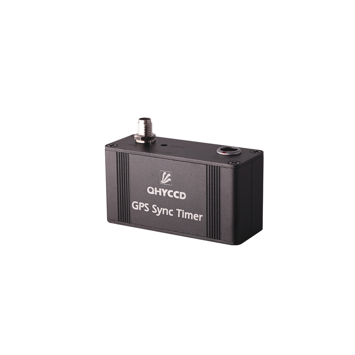
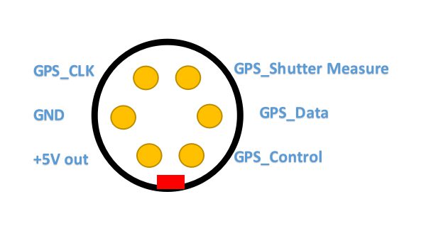
MODE1: 6PIN QHY-GPSBOX mode
In this mode, Four GPIO port is configed as gps_clock, gps_data, shuttermeassure,gps_control. You can connect with QHYCCD-GPSBOX. The camera will output the shuttermeassure signal to GPSBOX and GPSBOX will send the data to camera. Camera will replace the first some pixel to the gps data .
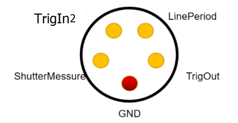
MODE2: 5PIN Generic TrigOut / TrigIn mode
In this mode, Four GPIO port is configed as TrigOut, ShutterMeassure, TrigIn, LinePeriod . Only TrigIn pin is input direction and other three pin is output direction.
In some camera, like QHY4040,QHY2020,QHY42PRO,QHY6060, The shuttermeassure waveform rising edge is the start exposure time and falling edge is the end exposure time 。 in other camera like QHY600,QHY268, QHY411,QHY461 etc, The shuttermeassure waveform is the vsync signal . It is near to the end of exposure time of the first row. For more information of TrigOut,LinePeriod. Please see some other document of QHYCCD supplied.
MODE3: 4PIN GPS Card TrigIn mode
In this mode. there is two pin is configured as ouptut . Both of the two pins is the shuttermeassure signal but one of it is inverted. This is suitbale for some GPS card which need such a “differencial signal”. But please note this is not LVDS signal. It is still TTL signa,
MODE4: Multi-Camera Master Mode
TO BE ADDED
MODE5: Multi-Camera Slave Mode
TO BE ADDED
MODE6: LED Calibration Mode
By using the controlled LED pulse, we can calibrate the distance from the TrigOut or ShutterMeassure signal to the real pixel/row start/end exposure time. To use this mode. You need to connect a LED to one GPIO pin and let the camera capture the flash that output from the camera. The start time and end time relative with the TrigOut/ShutterMeassure can be set by APIs. By check if the camera captured this pulse. You will get the delta time of the TrigOut/ShutterMeassure signal and use it to calibrate the messured GPS time.
| mode 0 | mode 1 | mode 2 | mode 3 | mode 4 | mode5 | mode6 |
| GPIO1 | GPSBOX_Control | ShutterMessure+ | ShutterMessure+ | n.a | n.a | ShutterMessure+ |
| GPIO2 | GPSBOX_Data (IN) | TrigIn2 | ShutterMessure- | n.a | n.a | TrigIn2 |
| GPIO3 | GPSBOX_ShutterMessure | LinePeriod | n.a | HSYNC(OUT) | HSYNC(IN) | LinePeriod |
| GPIO4 | GPSBOX_CLK | TrigOut | n.a | VSYNC(OUT) | VSYNC(IN) | LED(OUTPUT) |
| GND | GND | GND | GND | GND | GND | GND |
UVLO Function Introduction
UVLO(Under Voltage Locking), is primarily intended to protect the electronic device from damage caused by abnormally low voltages. Now only QHY600, QHY268, QHY410, QHY411, QHY461, QHY533 cameras have UVLO Protection.
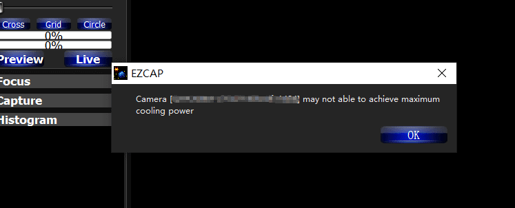
UVLO warning execution
After a warning is given, the camera firmware will automatically turn off the cooler and will turn on the camera’s TEC protection mode. After the camera is reconnected, it will always work in TEC protection mode (maximum power cooler power will be limited to 70%). Since many times the voltage shortage is caused by the high resistance of the power supply cable itself, resulting in a large voltage drop at high currents, the voltage will usually rise after the power is limited. But limiting the power will affect the cooling temperature difference. Therefore, it is recommended that users first check the power supply cable to solve the problem of excessive resistance of the power supply cable.
If the user has solved the problem of insufficient supply voltage, the TEC protection mode can be removed through the menu of EZCAP_QT.
How to improve the power supply?
- Make sure the output voltage of the AC adapter is not less than 12V and the maximum output current can reach 4A or more. Otherwise, the AC adapter itself will not meet the power demand of the camera and it may cause a low voltage problem.
- Make sure that the 12V power supply cable connecting the AC adapter to the camera has a low impedance. The impedance of the positive and negative paths should not exceed 0.1 ohms each. Or the total impedance (positive + negative) should not exceed 0.2 ohms. Otherwise, the power supply cable should be thickened.
- When using battery power, it is recommended to add a 12V output voltage regulator. If the battery is connected directly, usually the battery voltage reaches 13.8V when fully charged, and will gradually drop during use. It is easy to cause the camera to reach the low-voltage detection threshold.
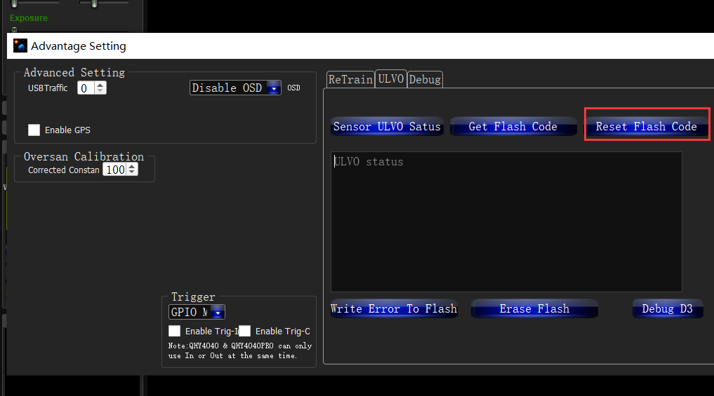
How to clear the TEC protection status triggered by UVLO?
Once a UVLO event occurs, the camera will automatically memorize it and will work in a protected mode at a maximum of 70% power after reconnection. This memory can be erased as follows:
After you find the system error, you need to turn off the device and check the power supply. After inspecting the problem, open the ezcap software and select “Camera Settings” – “Preferences” – “Reset Flash Code” to reset the error status.
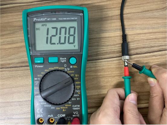
Why does the warning appear even though the power supply voltage is 12 V?
- The voltage measured inside the camera is the voltage reaching the camera, not the voltage at the power adapter end. Therefore, the voltage measured at the power adapter end does not reflect the voltage received at the camera end. This is because the power cable has its own resistance. If the resistance is large, it will cause a large voltage drop. The voltage drop can be calculated by U = I * R. So if the power cable has a resistance of 0.2 ohms, it will produce a voltage drop of 3.3 * 0.2 = 0.66V. If the power adapter output is 12 V, the voltage reaching the camera is 12 – 0.66 = 11.34 V. To actually measure the input voltage at the camera end, you can refer to the photo below.

- For cameras produced after September 2021, the UVLO is detected by communicating directly with the power manager, and the UVLO code that appears is 9, while for cameras produced before, the indirect detection method is used, and the UVLO code that appears is 3. The indirect detection method will detect UVLO except for the low voltage problem, and any other accident that causes CMOS not to work will also trigger the UVLO=3 alarm, for example, the camera is subject to severe electromagnetic interference, causing registers inside the CMOS not to work. Therefore, if UVLO=3 occurs, it is recommended to contact QHYCCD technical support for further judgment.
- Using older versions of drivers and firmware may cause false positives (UVLO=9). Please make sure that ALL-in-one SDK version is out of stable version 2021.10.23 or higher. Please disconnect the 12V power supply during the driver installation.
QHYCCD BURST Mode
QHYCCD BURST Mode
Added functions related to BURST mode in SDK. Currently, cameras that support Burst function include QHY600, QHY411, QHY461, QHY268, QHY6060, QHY4040, QHY4040PRO, QHY2020, QHY42PRO, QHY183A
This mode is a sub-mode of continuous mode. This function can only be used in continuous mode. When this function is enabled, the camera will stop outputting image data, and the software frame rate will be reduced to 0. At this time, send relevant commands to the camera, and the camera will Output the image data with the specified frame number according to the settings, for example, set Start End to 1 6, the camera will output the image data with the frame number 2 3 4 5 when receiving the command.
Note:
1. When using Burst mode in fiber mode, the first Burst shot will be one less. For example, if the start end is set to 1 6, the output of 2 3 4 5 is normal, but in fact, only 3 4 will be output during the first burst shot. 5, 2 will not be received, the second and subsequent shots can normally obtain Burst images 2 3 4 5. This problem will be fixed later.
2. QHY2020, QHY4040 found that the frame number that came out when the exposure time was short is [start+1,end-1] but the one that came out under long exposure was [start+2,end]
3. When the camera is just connected, if the set end value is relatively large, the camera will directly output the picture after entering the burst mode. Therefore, it is necessary to set the camera to enter the IDLE state and then set the start end and related burst operations.
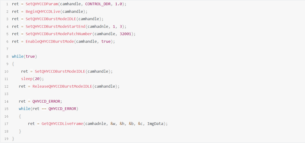
The following is the usage of Burst mode related functions:
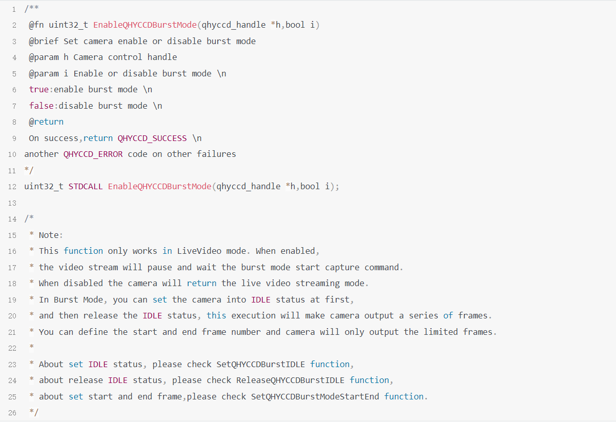
1.EnableQHYCCDBurstMode
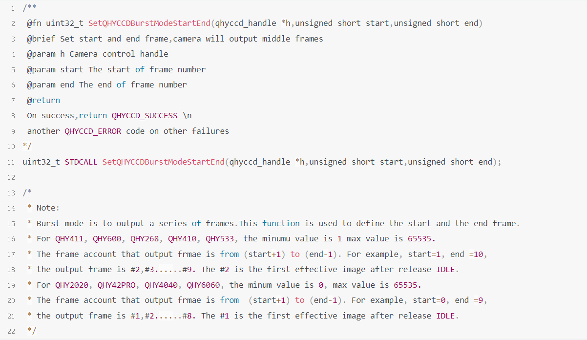
2.SetQHYCCDBurstModeStartEnd
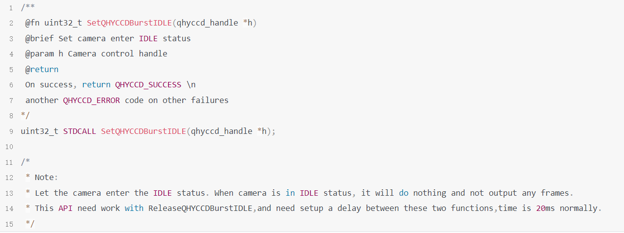
3.SetQHYCCDBurstIDLE
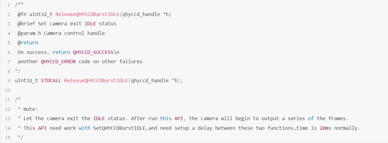
4.ReleaseQHYCCDBurstIDLE
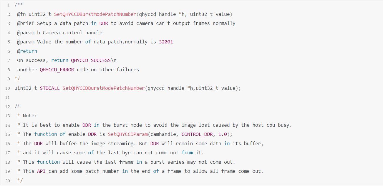
5.SetQHYCCDBurstModePatchNumber
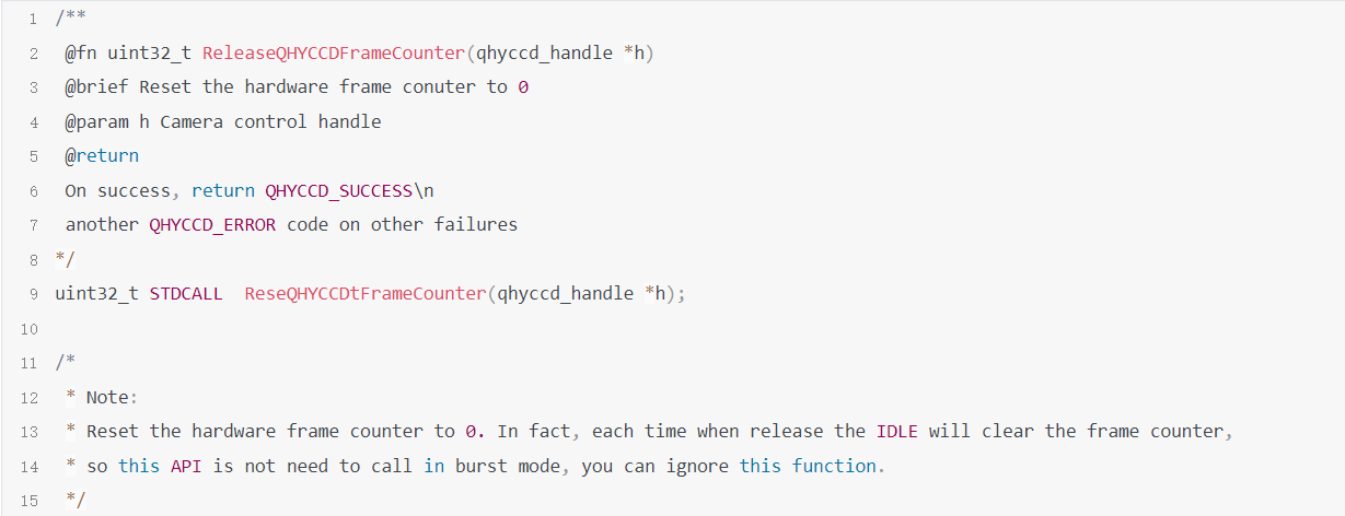
6.ReseQHYCCDtFrameCounter
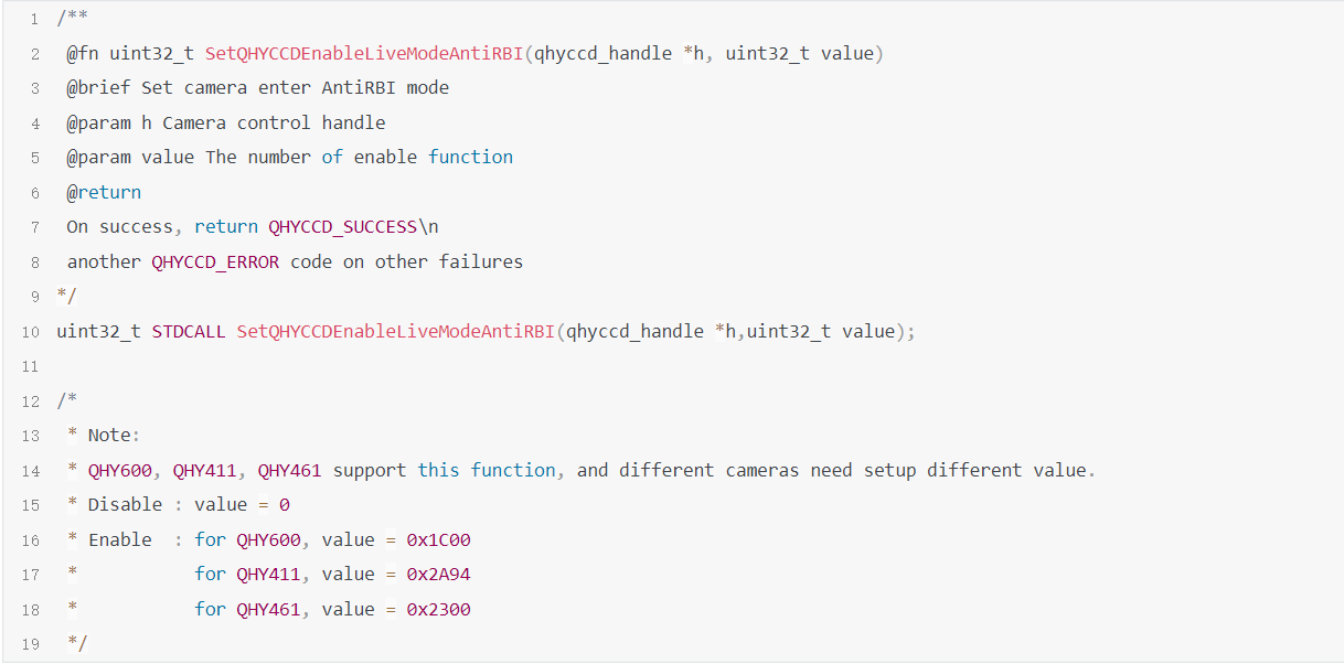
7.SetQHYCCDEnableLiveModeAntiRBI
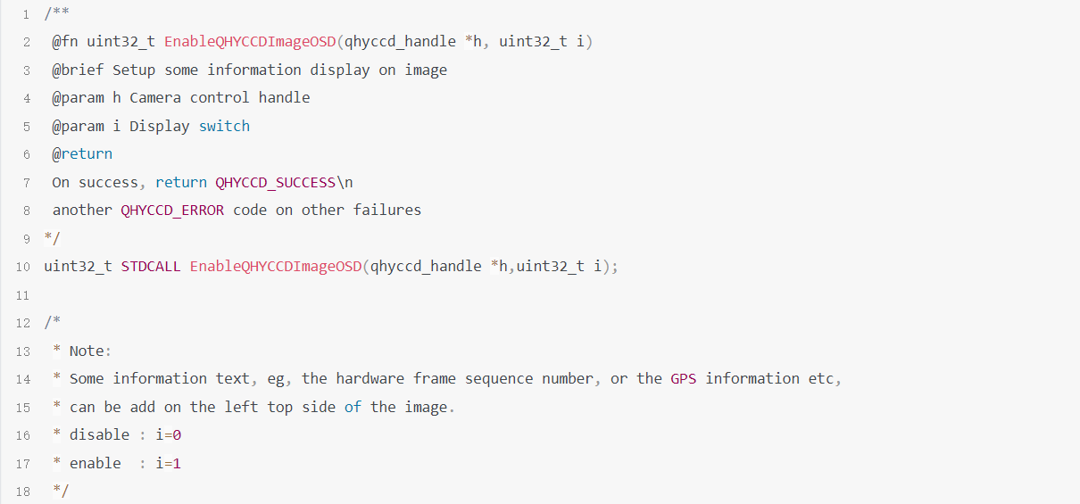
8.EnableQHYCCDImageOSD
Sample Code
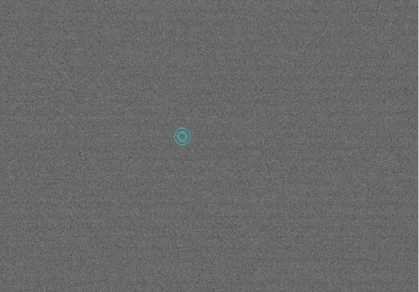
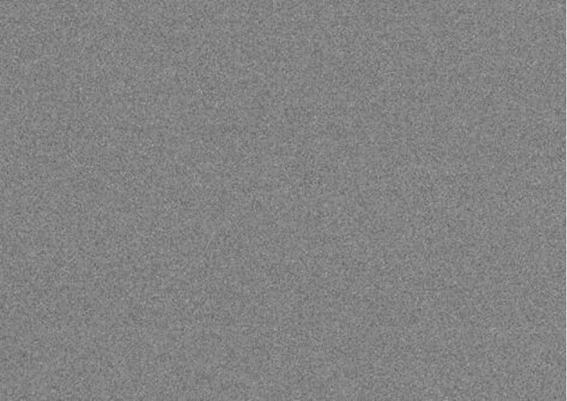
QHY411/461 has abnormally large thermal noise FAQ

The abnormally large thermal noise in the picture above is caused by the failure of the internal voltage to start after the camera is powered on. You can power on the camera again and take an image to see if it can be recovered.
If you encounter this problem during use, you can contact QHYCCD for hardware upgrade. This type of camera purchased before 2022.8.25 may have this problem.
Equipment maintenance
Drying the Camera CMOS Cavity
Since QHY411 is usually connected to a large telescope, especially the prime focus of a large telescope, it is not convenient to disassemble it at this time. Therefore, QHY411 is designed with a built-in drying system to facilitate maintenance work and solve the problem of maintenance-free long-term use.
QHY411 has a built-in CMOS sealed chamber humidity sensor and a built-in circulation pump. The real-time humidity value of the sealed chamber can be read through the API. When the humidity is high, the maintenance personnel should start the camera’s built-in circulation pump to dehumidify the air in the sealed chamber. Since the sensor and pump are both built-in to the camera and controlled by the QHYCCD API, this design is very suitable for remote operation.
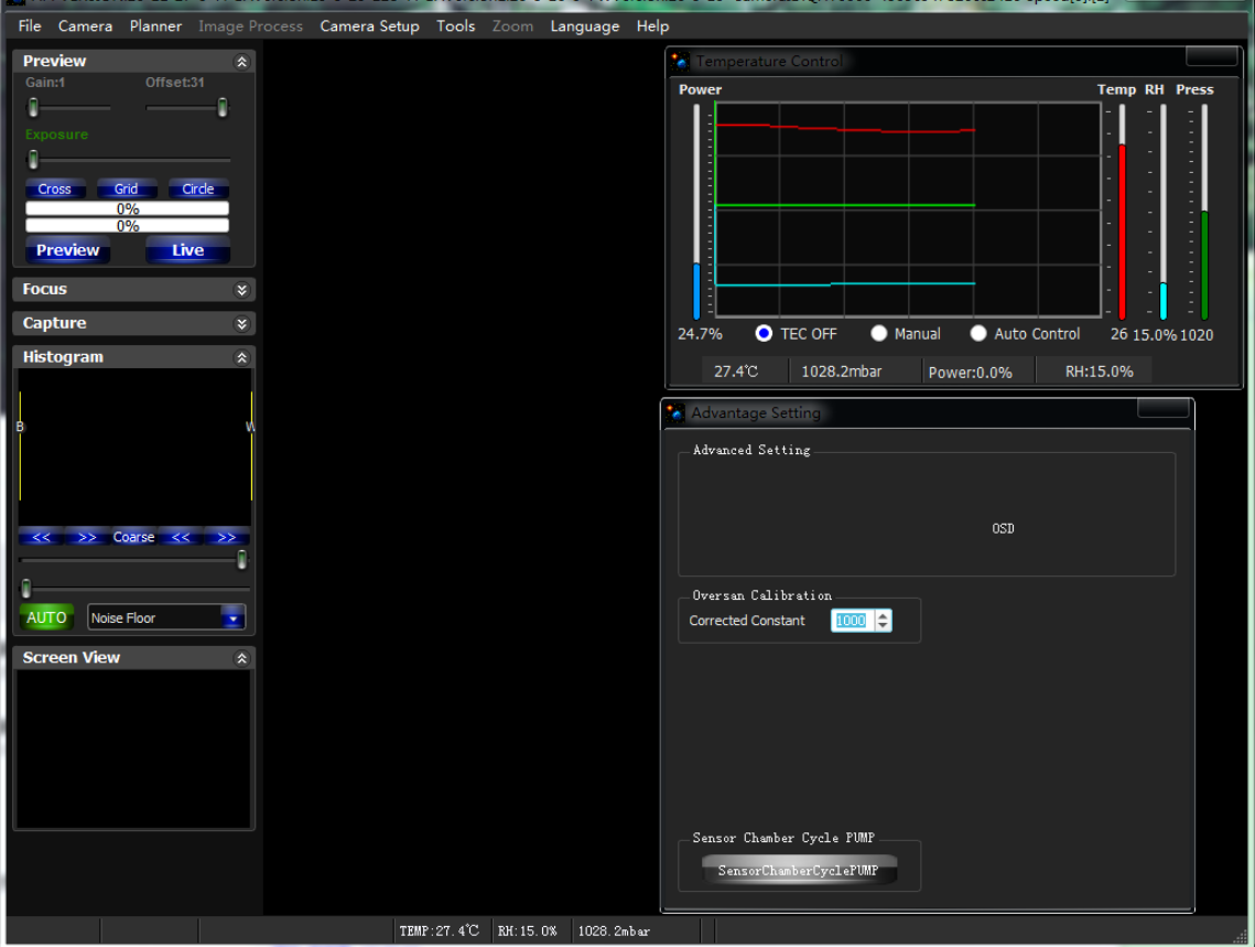
EZCAP-QT can realize the functions of real-time humidity reading and control of the circulating drying pump as shown in the figure. (Note: Use EZCAP_QT software to turn off camera cooling (TEC OFF) and observe the humidity display curve (RH) of EZCAP_QT. The cyclic dehumidification function in the software was added on 2020-11-27. Please use the version on 20-11-27 or later.)
Start the camera’s built-in air circulation pump (click SensorChamberCyclePUMP)
The display value of the humidity display curve decreases. After about 5 minutes, the software automatically turns off the air circulation pump and completes the camera drying process (If the humidity curve is still not ideal, please restart the air circulation pump in the software.)
If you need secondary development, please refer to:
Instructions for the switch pump API function:
uint32_t SetQHYCCDParam(qhyccd_handle *handle, CONTROL_ID controlId, double value)
Usage:
SetQHYCCDParam(camhandle,CONTROL_SensorChamberCycle_PUMP,value)
value=1:pump on
value=0:pump off
Preventing fogging on the optical windows of CMOS sealed chambers
If the ambient humidity is very high, the optical window of the CMOS sealed cavity may have condensation problems. QHY411 has a built-in heating plate to heat the lens to prevent fogging. In most cases, it works very well. If the fogging problem still exists, please try the following methods:
1. Avoid pointing the camera to the ground. The density of cold air is greater than that of hot air. If the camera is facing downward, cold air will more easily contact the glass, causing it to cool down and fog up.
2. Increase the temperature of the CMOS sensor. You can slightly increase the temperature of the CMOS sensor to prevent the glass from fogging.
3. Check whether the heating plate is working. If the heating plate is not working, the glass will fog up very easily. Normally, the temperature of the heating plate can reach 65-70℃ in an environment of 25℃. If it does not reach that hot, it may be because the heating plate is damaged. You can contact us to replace the heating plate.
Replace QHY411/461 desiccant
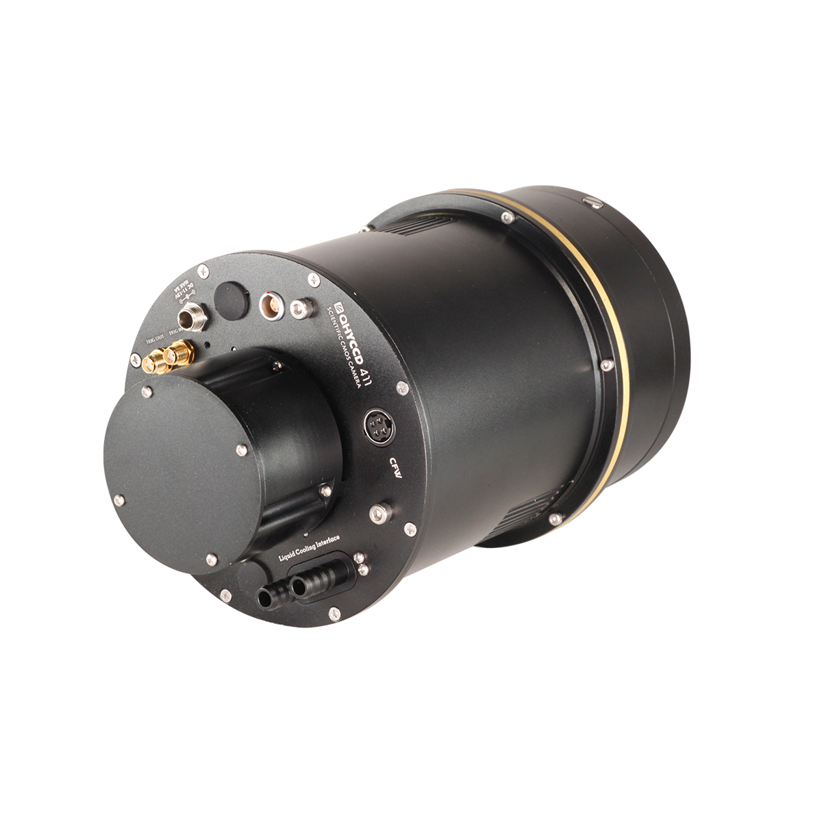
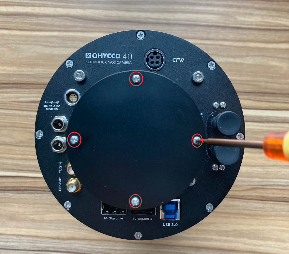
The cylindrical protrusion at the rear of the QHY411/461 camera is where the desiccant is stored. After long-term use, the internal desiccant will become ineffective and needs to be replaced to keep it dry. The replacement steps are as follows:
1. Open the 4 screws on the top of the drying cylinder.
2
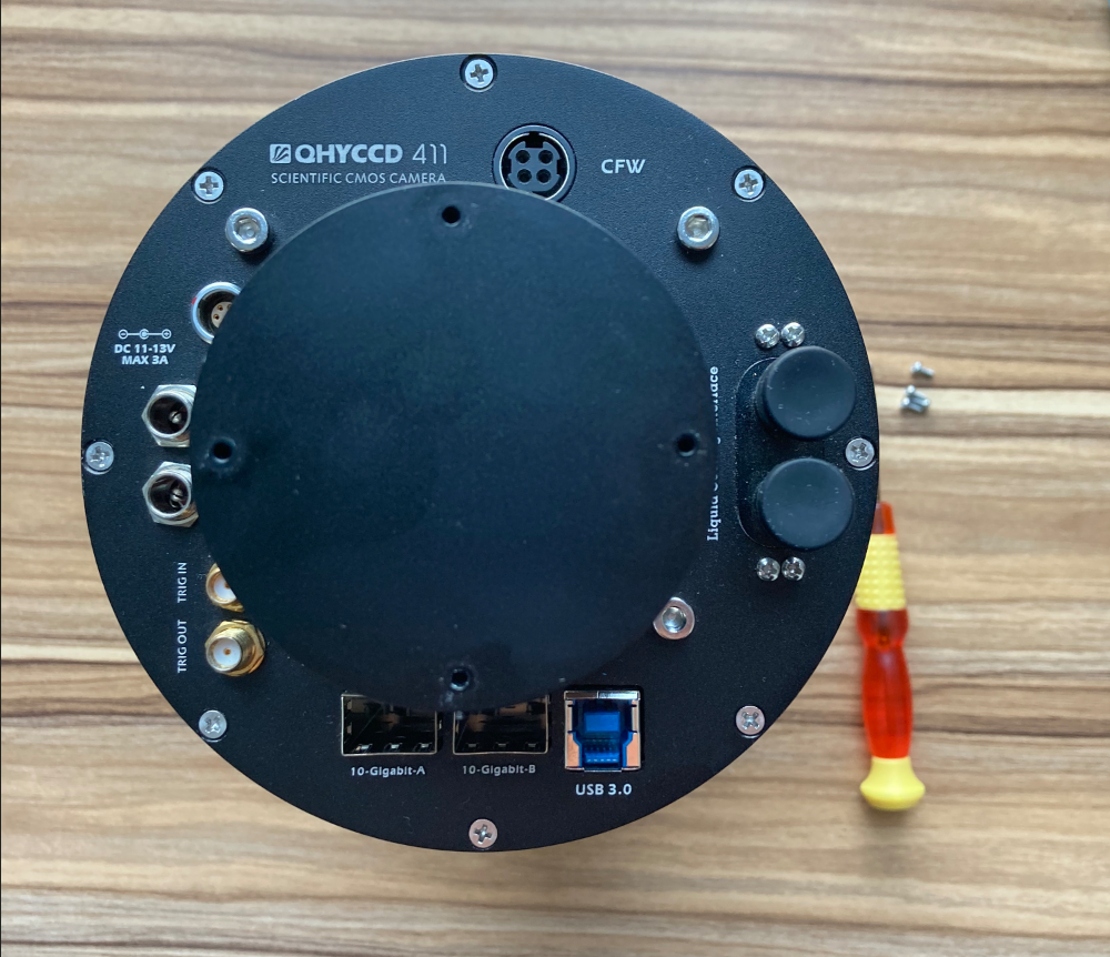
3. Remove the cover of the drying cylinder and replace the desiccant inside. (Blue desiccant turns pink after it expires. Orange desiccant turns green after it expires. Please pay attention to the color of the desiccant to determine whether the desiccant is effective.)
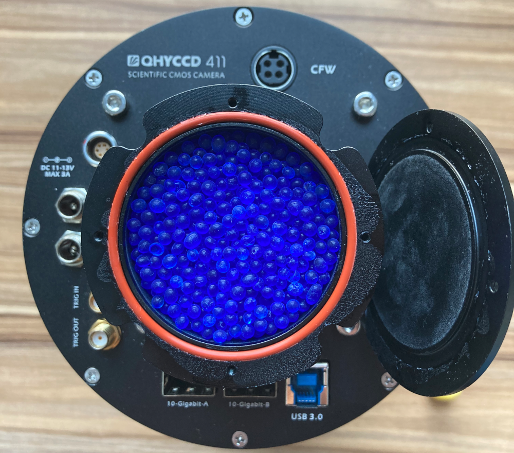
4. Seal the dryer cover.