

Overview
In this latest generation of sensors, the photodiode portion of the pixel well is physically deeper than in previous sensors, allowing photons of longer wavelengths to penetrate deeper into the substrate. This dramatically increases the sensor’s sensitivity to red and near-infrared (NIR) light. The sensor displays almost equal peak sensitivity to NIR light as it does to light in the visible spectrum.
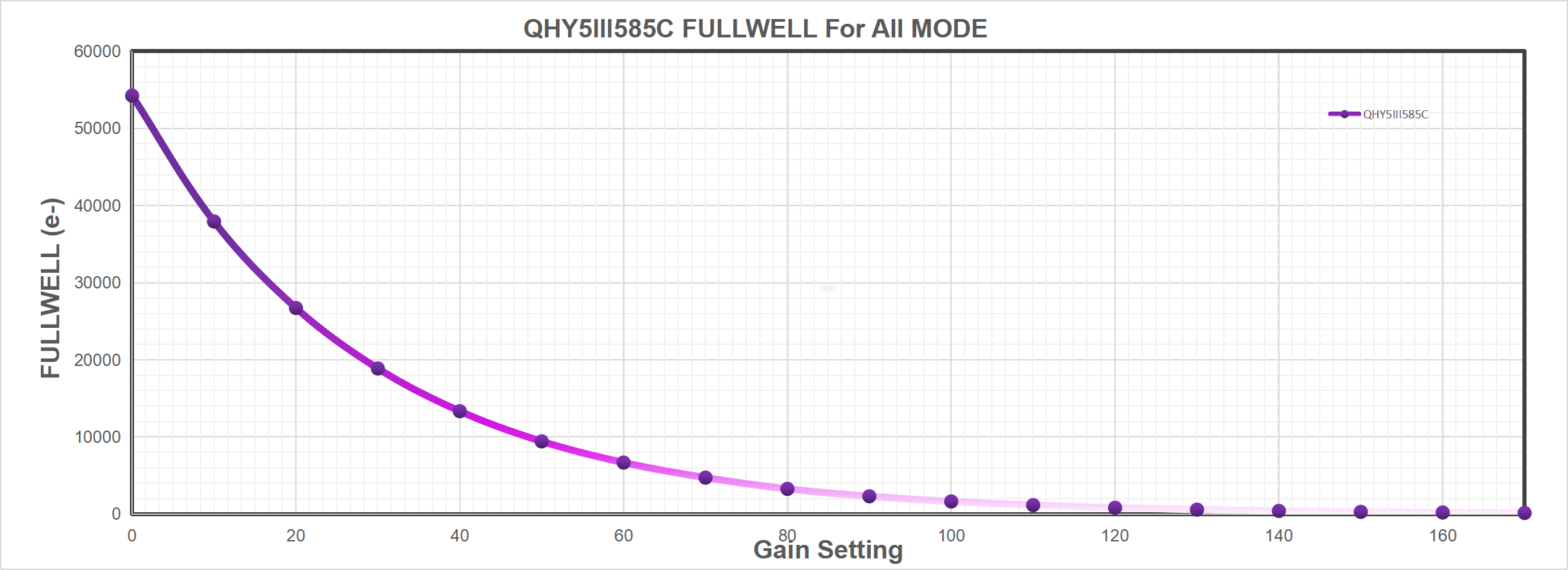
The IMX585 is a Sony Starvis II processor that enables high sensitivity and high dynamic range (HDR). It also improves sensitivity in the near-infrared range by approximately 1.7 times* compared to the IMX485. The new camera QHY5III585M/C has a large fullwell capacity of over 30ke-, approximately three times that of the previous generation QHY5III485C.
*This data is officially provided by Sony: https://www.sony-semicon.com/cn/news/2021/2021062901.html
QHY5IIISeries V2 Introduction
512MB DDR3
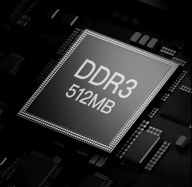
The QHY5III (Ver. 2) series planetary and guiding cameras are all equipped with a 512MB DDR3 image buffer which can effectively reduce the pressure on computer transmission, a great help for planetary photography which often requires writing a large amount of data in a short period of time. Some deep-sky astrophotography cameras on the market today only have 256MB, for example.
In comparison, the 512MB DDR3 memory of the new 5III (Ver. 2) series cameras represents a significant upgrade.
New Front-end Design with Better Compatibility
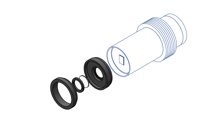
QHY5III (Ver. 2) series cameras have adopted a new front-end design with better compatibility.Here we only take QHY5III200M as example, however, ALL V2 cams in the future share these features.
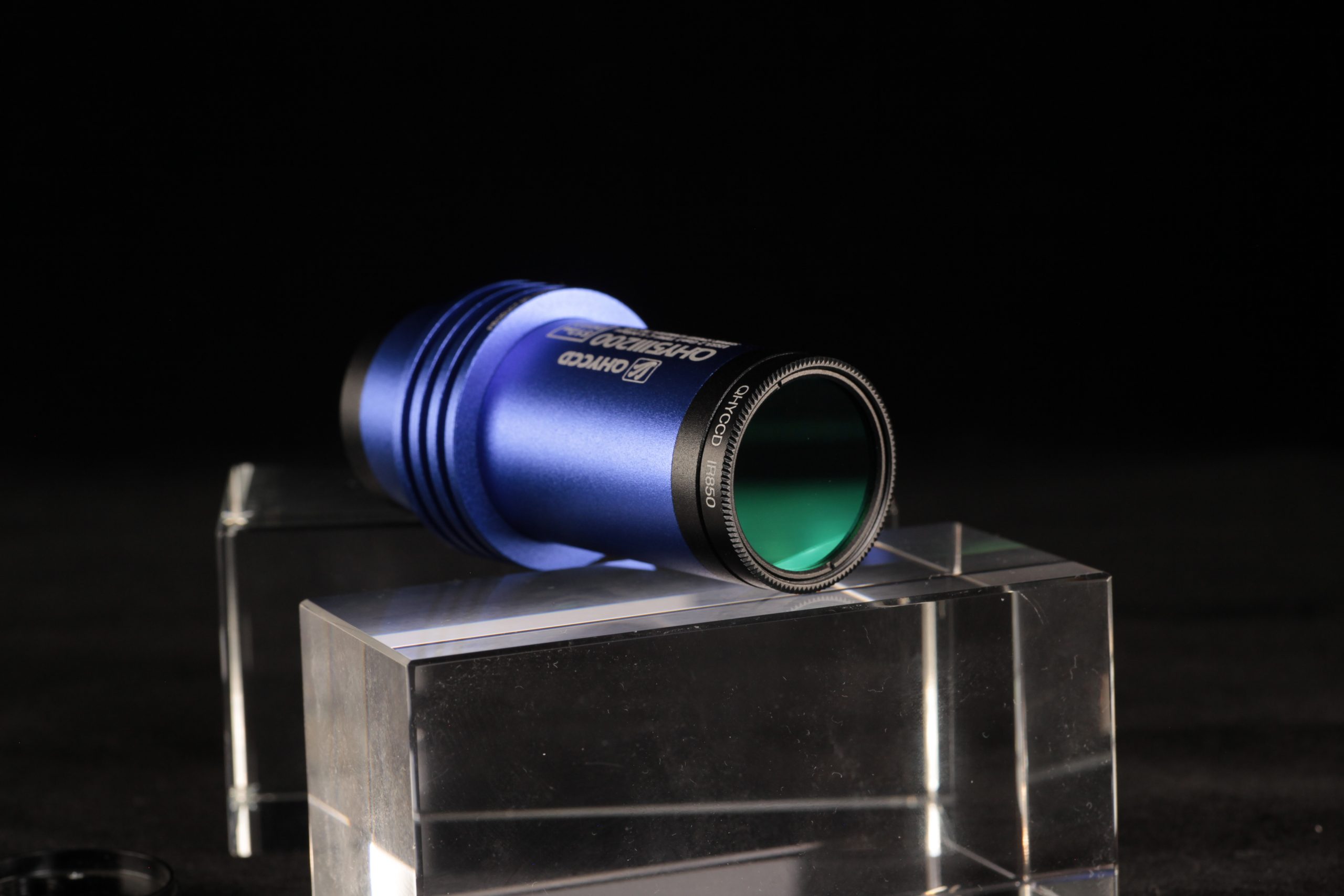
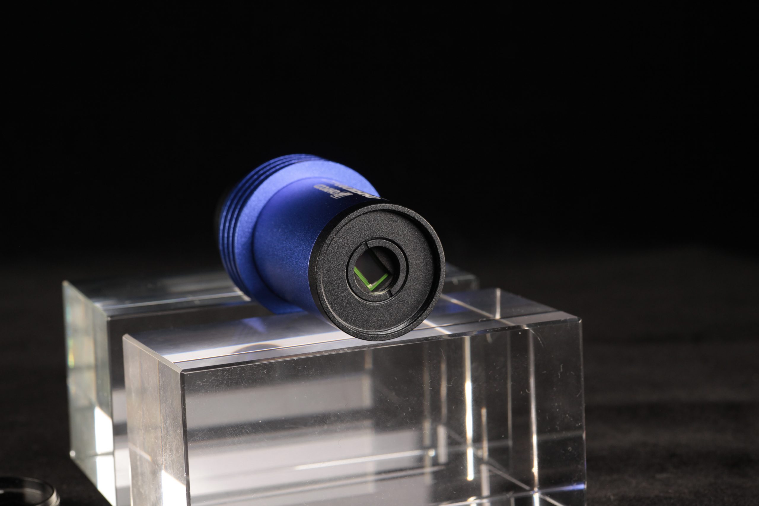
The BFL of V2 cam is only 8mm, which means you can easily compat a V2 cam with your OAG. The basic top adapter includes 1.25 inch threads and you can still use your 1.25 inch filter.
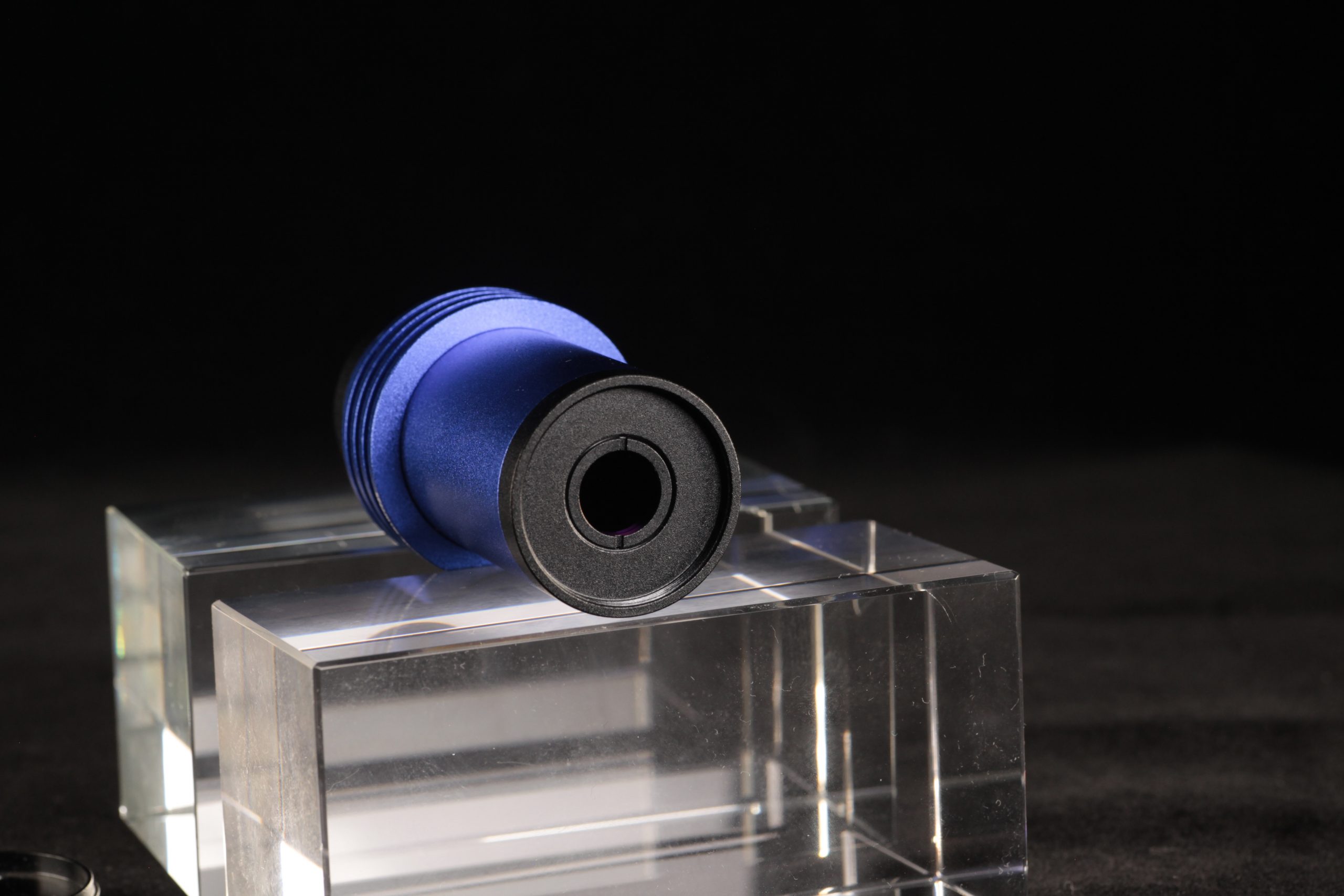
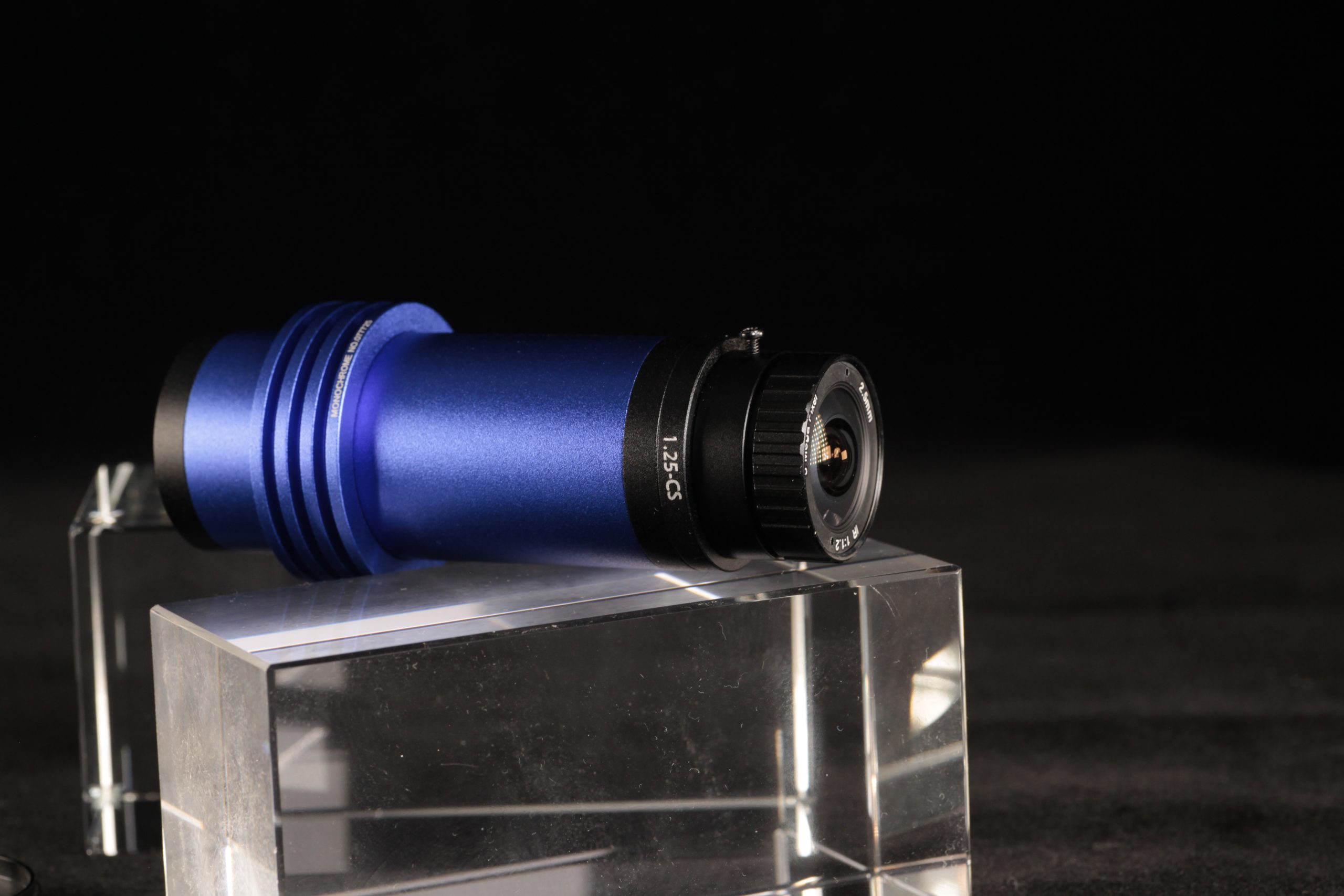
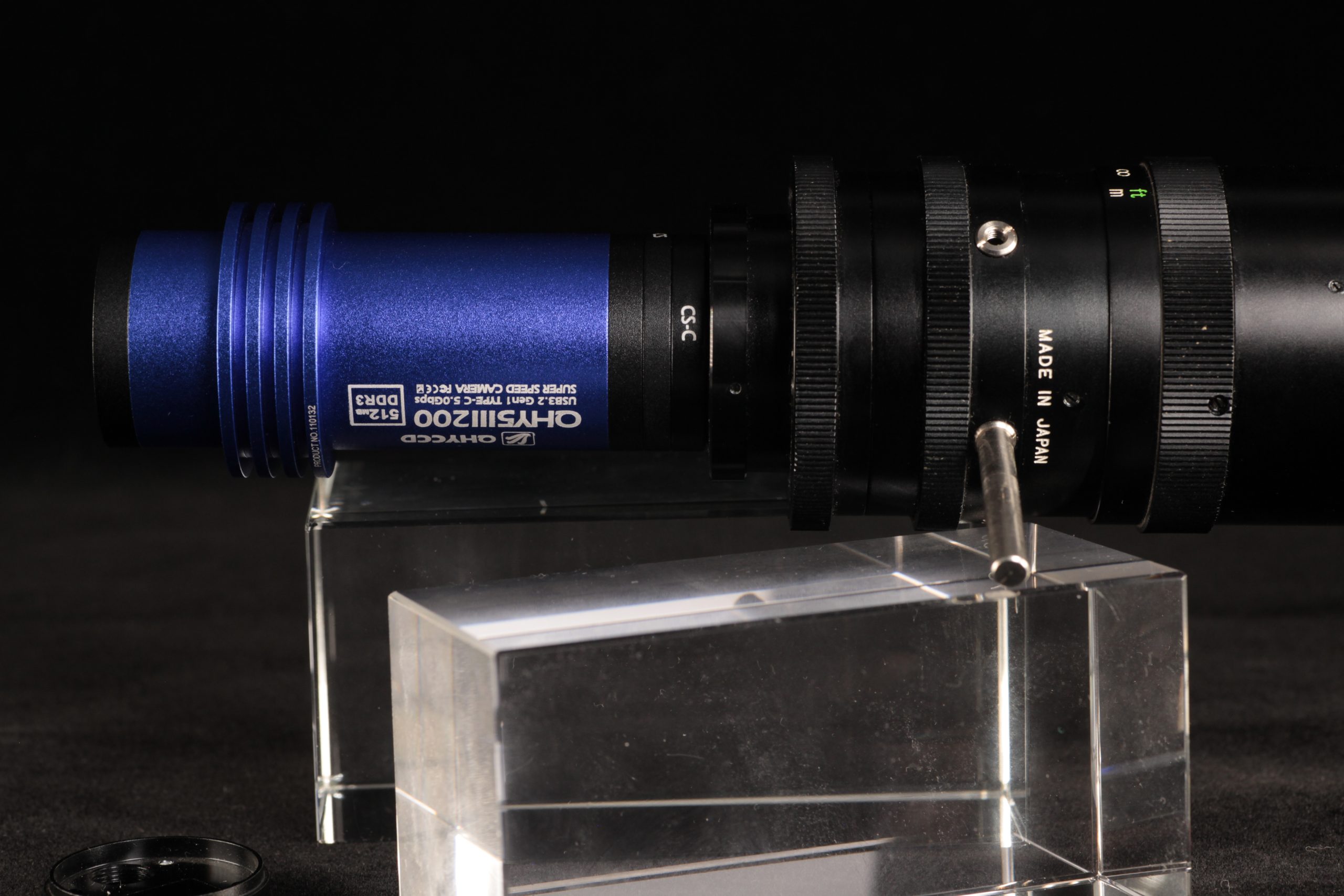
The top adapter glass of V2 can be easily swiched. One of the adavantage of changable top glasses is you can use one filter even you’re using Lens! You can add a 1.25inch-cs adapter to connect CS lens, or add a second CS-C lens for C-mount lens. The two adapters are all standard accessories of V2 cams.
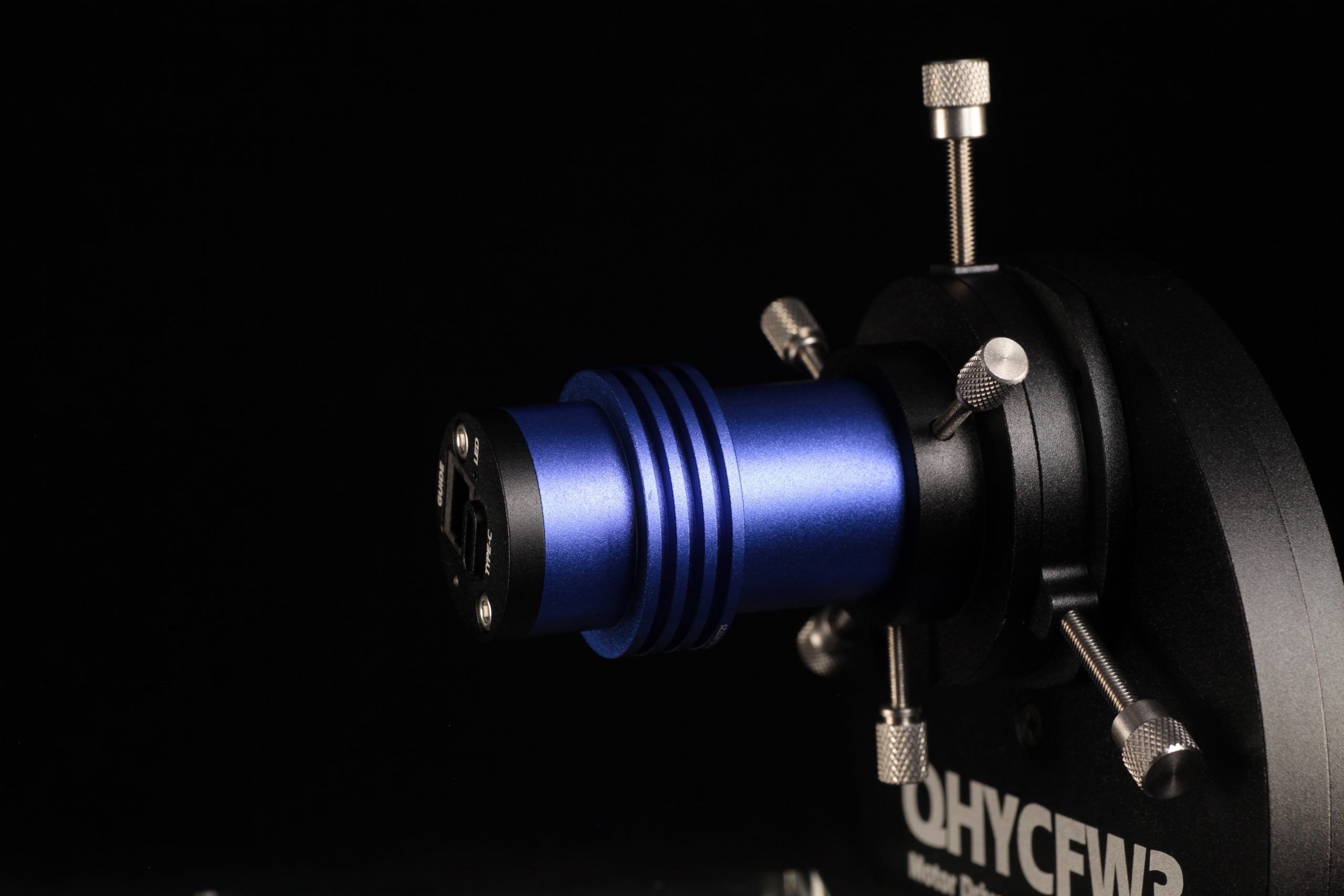
By the way, there’s a 1.25-inch filter wheel adapter to connect your mono planetary cam with the QHYCFW3-S filter wheel.
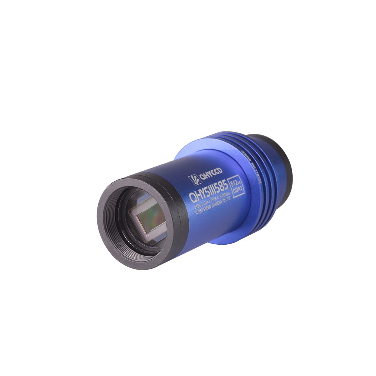
USB 3.2 Gen1 Type C Interface
 The new QHY5III (Ver.2) series cameras all use the USB3.2 Gen1 Type-C interface. Compared to the USB3.0 Type-B interface used in the previous generation, the Type-C interface has a longer life and is more flexible.
Tips: It is recommended to use the official standard Type-C data cable of QHYCCD. As the market is flooded with a large number of poor-quality Type-C cables, casual use may lead to the camera malfunctioning. If you use your own spare cable, please make sure it is a high-quality cable.
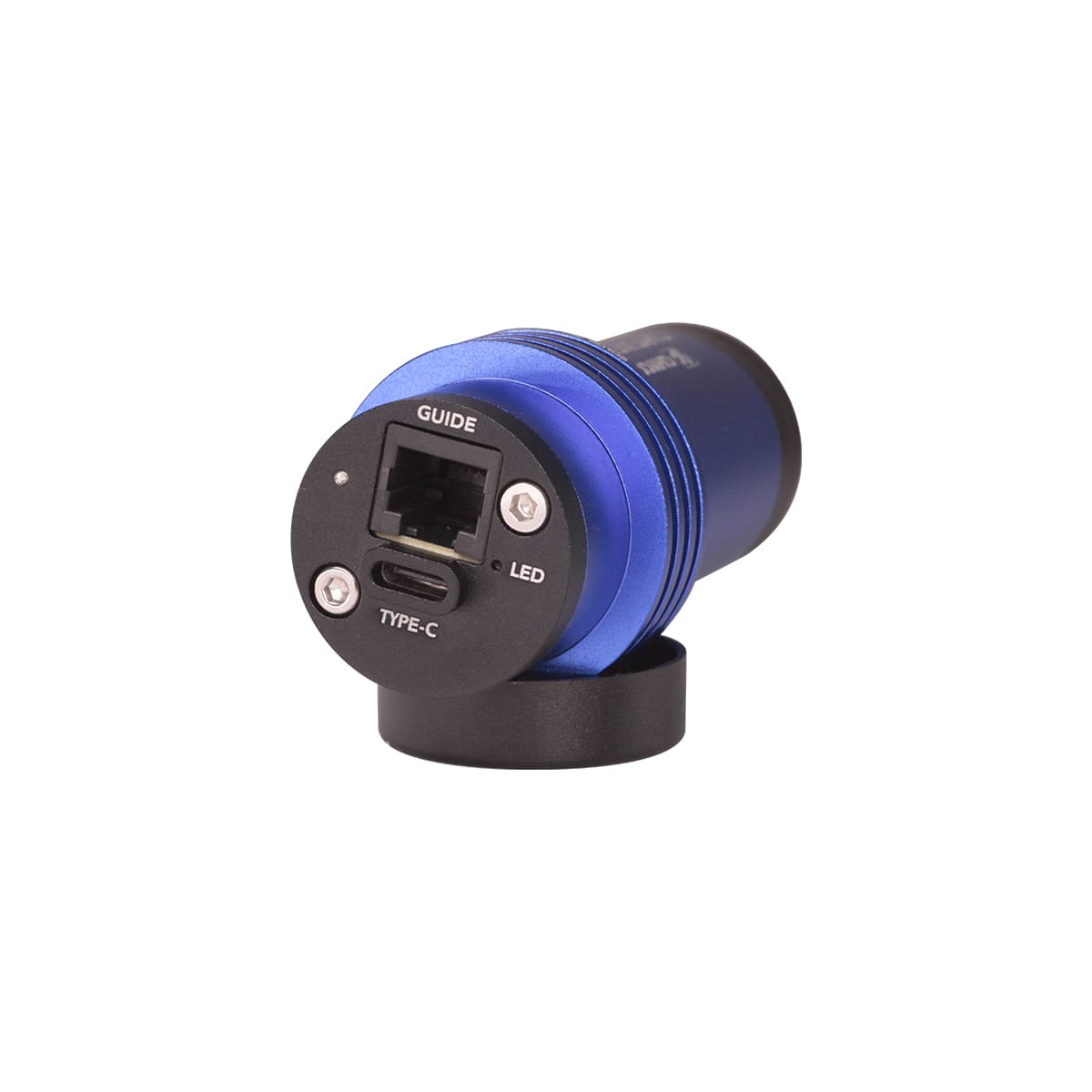
Universal Guiding Interface
The custom interfaces of the previous generation of planetary cameras and guiders has been replaced in the QHY5III (Ver.2) cameras with a more universal ST-4 compatible guiding interface. Now, even if the guiding cable is lost or damaged, you will be able to easily get a replacement on the market at a low cost.
Indicator LED
 The new QHY5III (Ver.2) series of cameras is equipped with a status indicator at the back of the camera. If the camera experiences an abnormal status, the multi-colored indicator light will help to determine the situation with different colors signifying different conditions. During normal operation this indicator light is off, so there is no worry about light contaminating the image.
Sample Images
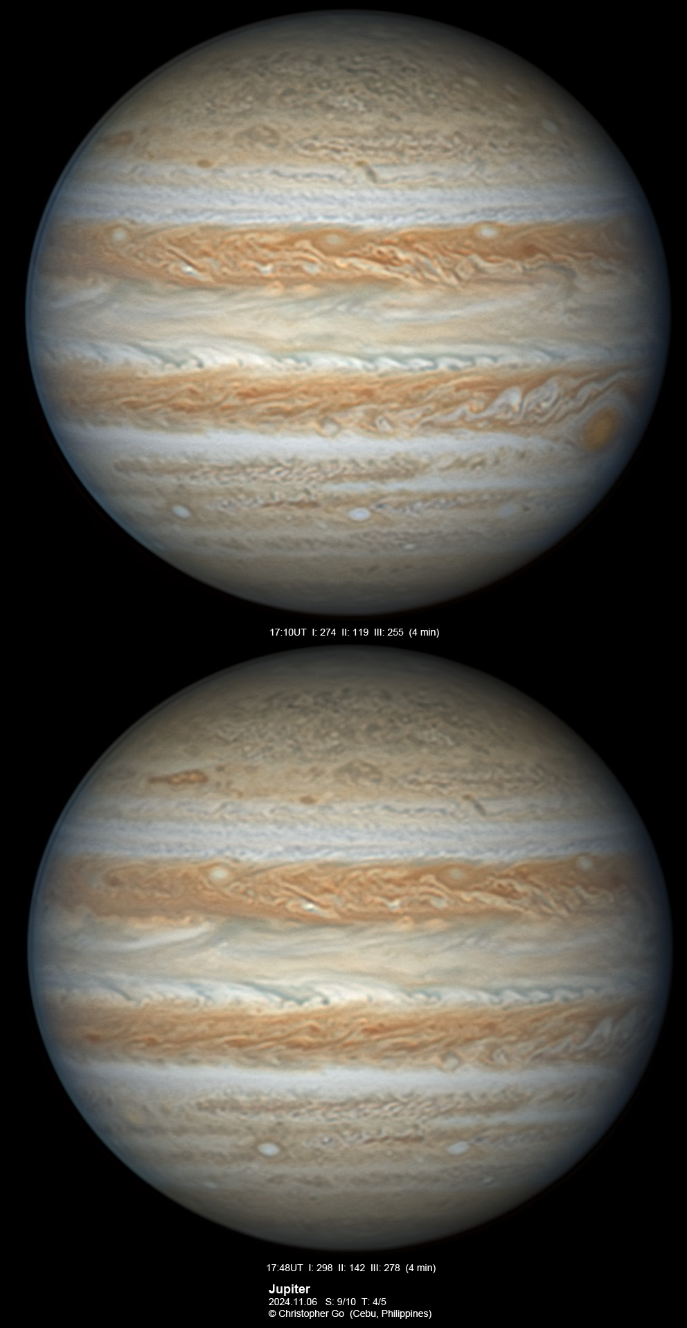
Jupiter captured by Christopher Go
Equipment: Celestron C14 Telescope+QHY5III585C+Astrophysics AP900GTO mount
Specification
| Model | QHY5III585M/C |
| Image Sensor | Sony IMX585 |
| Mono/Color | Both |
| FSI/BSI | BSI |
| Sensor Size | 1/1.2inch |
| Pixel Size | 2.9μm*2.9μm |
| Effective Pixel Area | 3856*2180 |
| Effective Pixels | 8.4 Megapixels |
| Full Well Capacity | 52ke- |
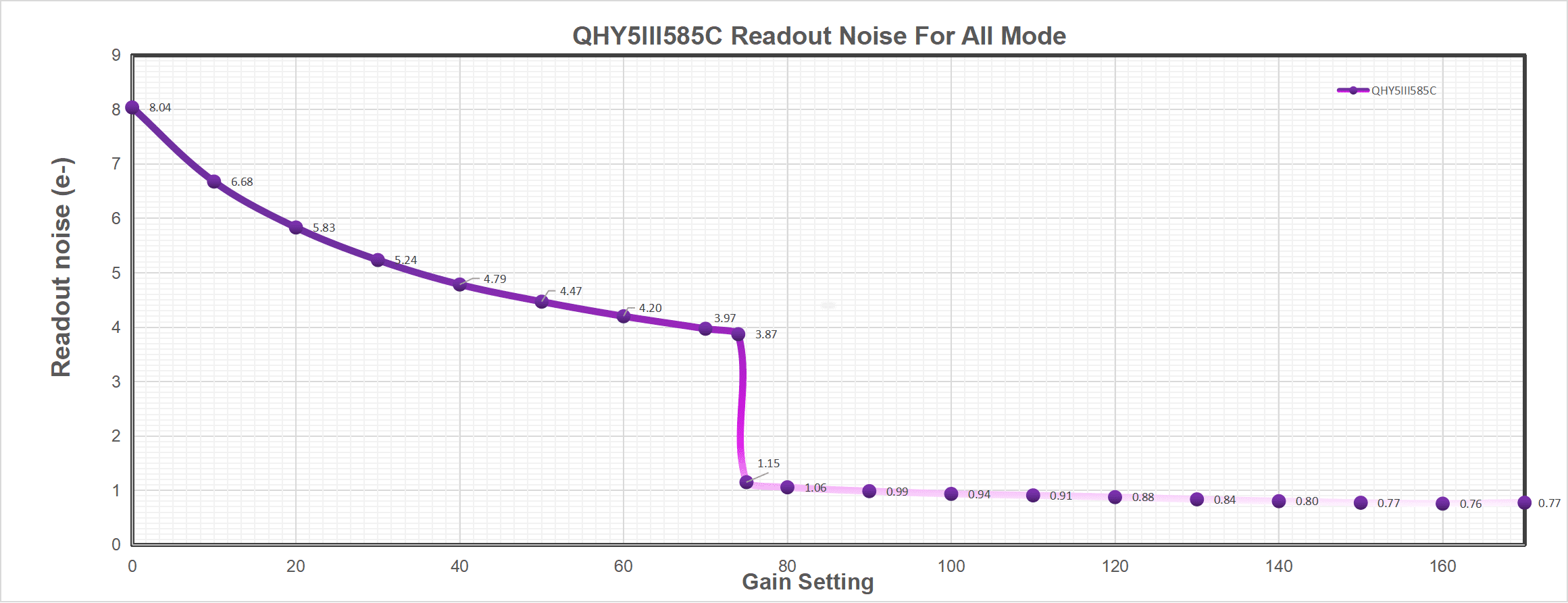
| Read Noise | 0.77e- to 8e- |
| A/D | 12-bit (output as 16-bit and 8-bit) |
| Built-in Image Buffer | 512MB DDR3 Memory |
| Full Frame Rates | 41.5FPS@8bit 23.5FPS @16bit |
| ROI Frame Rates | Full Resolution
1080Lines, 82FPS@8bit, 47FPS@16bit Full Resolution(After updating the driver version 2025.6.13, the ROI frame rate is improved as follows) |
| Exposure Time Range | 11μs-900sec |
| Shutter Type | Electronic Rolling Shutter |
| Computer Interface | USB3.0 Type-C |
| Guide Port | Standard ST-4 Style |
| Telescope Interface | 1.25-inch, with CS and C-Mount |
| Optical Window | M: AR Anti-reflection Glass C: IR-Cut Filter |
| Extra Filter | IR850nm Filter Included IR-Cut filter Included |
| Back Focal Length | 17mm (with adapter); 8mm(without adapter) |
| Weight | 90g |
Cures
Mechanical Dimensions

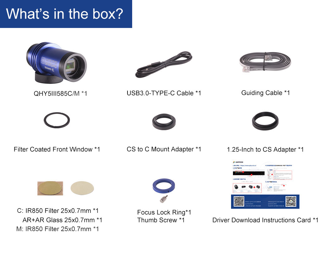
Accessories
User Guide
Install All-in-one Driver Pack
Before Start: Input Voltage Requirements
The camera requires an input voltage between 11V and 13.8V. If the input voltage is too low the camera will stop functioning or it may reboot when the TEC power percent is high, causing a drain on the power. Therefore, please make sure the input voltage arrived to the camera is adequate. 12V is the best but please note that a 12V cable that is very long or a cable with small conductor wire may exhibit enough resistance to cause a voltage drop between the power supply and the camera. The formular is: V(drop) = I * R (cable). It is advised that a very long 12V power cable not be used. It is better to place the 12V AC adapter closer to the camera.
First connect the 12V power supply, then connect the camera to your computer via the USB3.0 cable. Make sure the camera is plugged in before connecting the camera to the computer, otherwise the camera will not be recognized. When you connect the camera for the first time, the system discovers the new device and looks for drivers for it. You can skip the online search step by clicking “Skip obtaining the driver software from Windows Update” and the computer will automatically find the driver locally and install it. If we take the 5IIISeries driver as an example (shown below), after the driver software is successfully installed, you will see QHY5IIISeries_IO in the device manager.
Please note that the input voltage cannot be lower than 11.5v, otherwise the device will be unable to work normally.
Install "All-In-One" System Pack
All-in-one Pack supports most QHYCCD models only except PoleMaster and several discontinued CCD cameras.
Download Page: https://www.qhyccd.com/download/
Video Tutorial: https://www.youtube.com/embed/mZDxIK0GZRc?start=1
- Since most of the contents of All-in-one package are plug-ins that support third-party software, the third-party capturing software that you want to use must be installed before the All-in-one package. Otherwise the program will report an error.
- ALL-IN-ONE Pack contains:
- System Driver, which is necessary for the camera operation and must be installed.
- WDM Broadcast Driver, which can provide a live signal to Obs and other live software, you can install it if you have such needs like opeing a live show.
- EZCAP_QT , which is developed by QHYCCD and can be used in QHY devices tests, and management of updates. So even if you won’t use EZCAP_QT for capturing, we suggest you install it.
- Ascom driver, which is necessary for the camera used in Ascom (the latest version of Ascom is 6.6).
- The two sorts of Ascom CFW Drivers correspond to two methods of controling the filter wheel: USB control and camera serial control. It is recommended that both drivers should be installed if you have a filter wheel.
- CP210X_VCP is a serial driver. Some computers come with the driver, but the computer without the driver may be failed of controling the filter wheel.
- SDKs for Third-party Software: Just pick and install the corresponding SDK according to the software you want to use. Don’t forget to check whether the software you are using is 32-bit or 64-bit and select the right SDKs.
- SHARPCAP is also included in the pack, you can choose 32-bit or 64-bit to install. This is authorized by SHARPCAP.
- QT LIB is a plug-in to ensure that 64-bit software can exeuate normally on some computers with poor compatibility.
- Difference between Stable version and Beta Version: Beta version is the latest version, which gives priority to support for the latest products (the stable version may not be compatible with those yet), and has some of the latest optimized ,but experimental features. The stable version is older than the beta version but more stable, so it is recommended for beginners who are not using the latest products.
- Don’t let the camera connect to the computer during the All-in-one pack installation process; connect it to the computer after all the installation is complete.
Using Software
Here we mainly take QHY5III462C as example. This User Guide can be applied to all QHY5III series Camera.
Using SharpCap
Connect the camera and run SHARPCAP. if everything goes well, the video screen will be displayed after the software is opened, you can see the current frame rate at the bottom right of the software.
If you open the software first, and then connect the camera, you can use Camera->Scan Camera in the menu bar to find the camera. After you find the camera, it will be displayed in the menu (such as QHY5III462C). Check it.
In order to ensure that the camera can run successfully, the software will start the camera at the lowest speed to avoid being stuck because sometimes the frame rate is too high and exceeds the transmission bandwidth of the computer. So the frame rate you see now is a lower frame rate, which will be much lower than the highest frame rate declared on the QHYCCD webpage.
After the camera starts normally, you can try to increase the frame rate. The method is to first set the exposure time to 1 ms, (too long exposure time will limit the frame rate), and then reduce the value of “USB Traffic” to increase the USB bandwidth, at this time you can see the frame rate will increase . If your machine’s CPU speed is fast enough, such as an I7-4 core computer, it should be able to reach the maximum frame rate. But please note that not all computers can reach the maximum frame rate, it has a certain relationship with the CPU occupancy rate, the computer’s energy saving settings, and even the performance of the motherboard. If you find that when the USB traffic is reduced to a certain level, the frame rate does not rise but decreases, so the performance bottleneck of the computer has been reached at this time, and the frame rate can no longer be increased. In addition, sometimes the performance of the computer’s graphics card will also have a certain impact on the frame rate, you can consider reducing the software’s ZOOM zoom. See if it helps increase the frame rate. Because the display of the screen will occupy the CPU performance, thereby reducing the rate at which the CPU acquires images, which affects the frame rate.
The following figure is the frame rate of QHY5III462C under good conditions. Under full resolution output, it can reach up to 135FPS under normal circumstances.

Adjust OFFSET. You will find that when the lens cover is closed and the image is completely black, the background of the image is still not completely black. Therefore, you need to adjust the OFFSET value to make the image darker. Generally speaking, for planetary shooting, setting the image background to very dark is not a big problem. For deep space shooting, a certain background should be retained, and it should not be completely black, otherwise it will lead to the loss of a weak background cloud.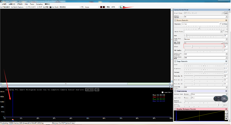
For planetary cameras, it is necessary to set OFFSET to a value as low as possible, so that the image with the lens cover as close to 0 as possible. Because the presence of bias may affect white balance. White balance is to multiply the red, green and blue data by a factor to compensate for the color cast caused by the different sensitivity to red, green and blue, or the different ratios of red, green and blue contained in the ambient light. But if there is a background offset, this offset will also be multiplied by a factor, and the resulting ratio is wrong. So if you don’t want to do accurate color calibration in the later stage, you can set the image background as close to 0 as possible in the early stage to get a simpler white balance. (For deep space, you must keep an image background, so it is recommended to shoot in deep space, do not do white balance here, let the RGB ratio settings be the same, and do white balance later).
If you want to try 16-bit images, it is best to set the USB bandwidth to a number greater than 5 (for QHY5III462C), otherwise the image will be stuck because of insufficient USB bandwidth. Then set it to “mono16” in the COLORSPACE box. At this time, the camera works in 16-bit mode (actually 12-bit, zero-fill the lower bits).
Check the “LX” mode to extend the exposure time range to long exposure time. QHY5III series cameras have an amplifier glow control circuit, which can significantly reduce the amplifier glow. Because it is an uncooled camera, it is recommended not to use too long exposure time, otherwise the background thermal noise will rise. For deep space shooting, it is recommended to use a short exposure + a large number of superimposed methods to shoot.
Using through ASCOM Platform
There are many astronomical software support ASCOM, you can connect QHY5III462C through ASCOM. Note that currently QHY5III462C only supports the ordinary ASCOM shooting mode, and does not yet support the ASCOM video mode. In order to obtain the maximum dynamic range and effect, the ASCOM driver uses the maximum number of digits transmission by default (for QHY5III462C, 12-bit), the image is stored in a 16-bit format, and the lower bits are filled with zeros.
Use MAXIMDL for Plantery Imaging
1. Download and install the ASCOM platform http://www.ascom-standards.org/
(Friendly reminder: If you can’t log in to the ASCOM platform download site, please use the scientific Internet, or contact the agent, or please provide help to the QHYCCD astronomical photography discussion group. In addition, the ASCOM installation process needs to rely on .NET support, if A dialog box pops up during ASCOM installation saying that the .NET component is missing, you need to install the .NET component first. This component can be downloaded from the Microsoft website).
2. If you have not installed the ASCOM driver for QHY5III, please download and install it at https://www.qhyccd.com/QHY5III.html
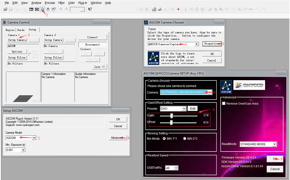
3. Run MAXIMDL software
4. In the camera model, select ASCOM (left picture), then select QHYCCD-Cameras-Capture (right picture)
5. In the properties, select QHY5IIIxxx Camera
6. Under normal circumstances, you can choose a gain of 1 and an offset of 10. Later, you can make certain adjustments according to the specific situation. The speed and overscan calibration options in the window are useless, please ignore.
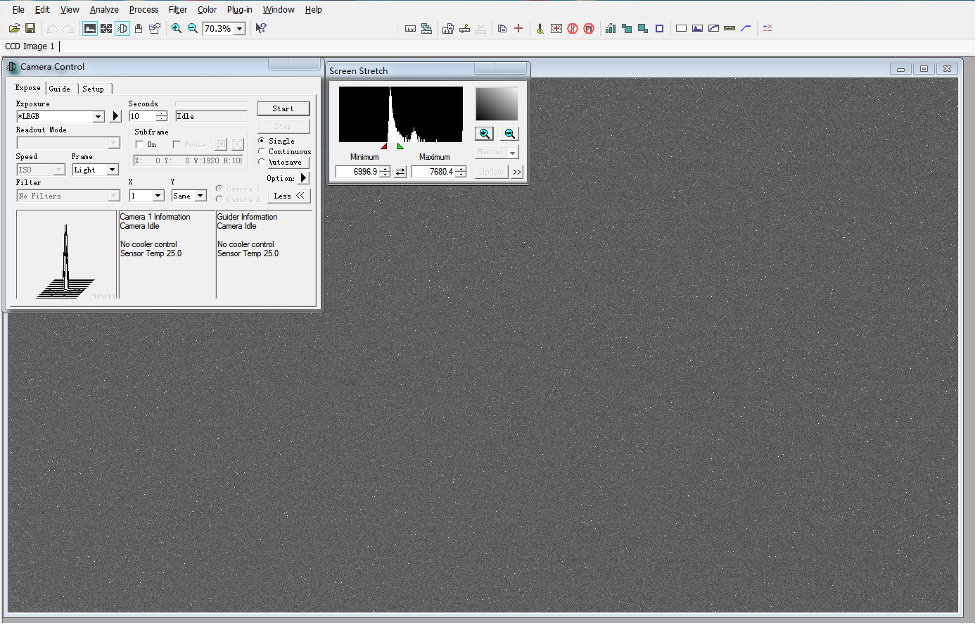
The following is a scene of QHY5III462C used in MAXIMDL. Please note that since the QHY5III series cameras do not contain a built-in large-capacity frame memory, they cannot buffer a frame of pictures. During transmission, frame loss may occur. If the frame is dropped, the camera will try to take another shot, so sometimes it may take longer to get a frame.
When changing the exposure time to a long exposure time, the CMOS chip may output a few frames of short exposure. These frames may be output, but the subsequent frames will be normal long exposure frames.
Using PHD for Guiding
You can use the PHD guide software and the camera’s built-in guide port to guide the star. The PHD guide software is also connected to QHY5III462C through ASCOM. In the camera button of PHDGudiing 2.5, select the connection method of ASCOM Camera and On-camera guide star.
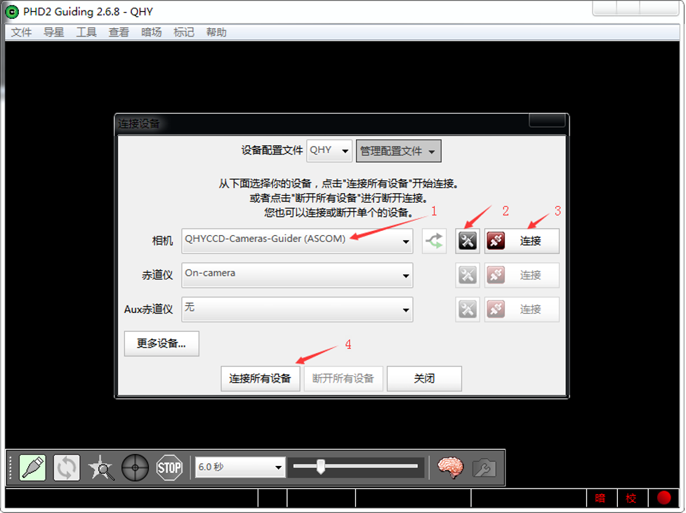
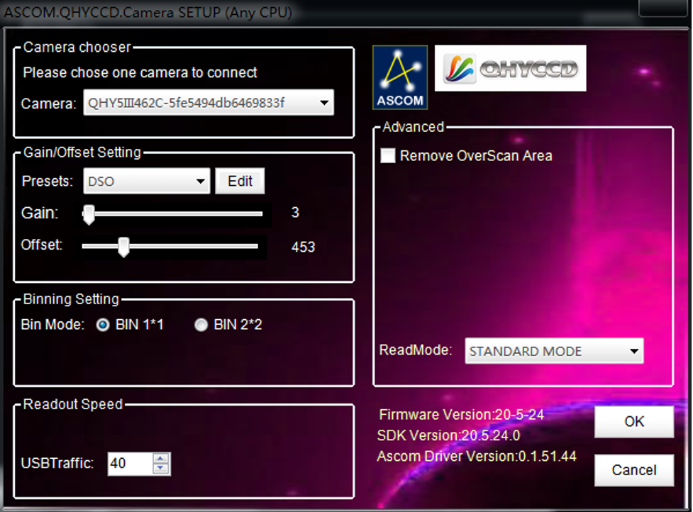
Select the Connect button, then the ASCOM camera chooser window appears, select QHYCCD-Camera-Capture in the camera list. Select QHY5IIIxxx camera. Set the proper Gain and Offset
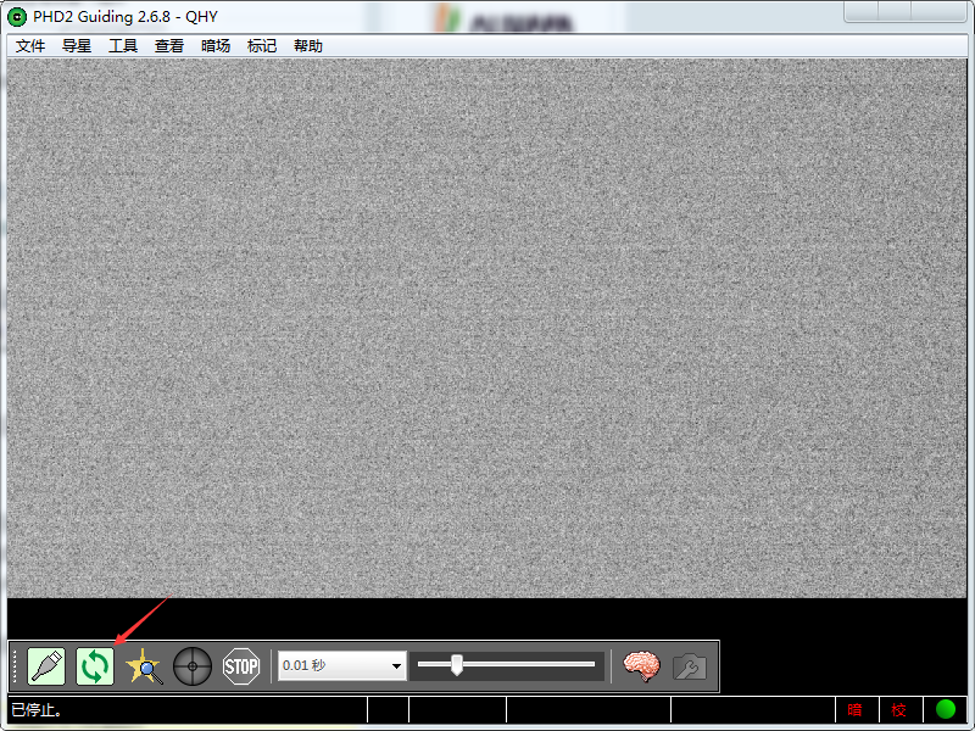
Connect the camera to the equatorial mount. Select the button to start continuous preview
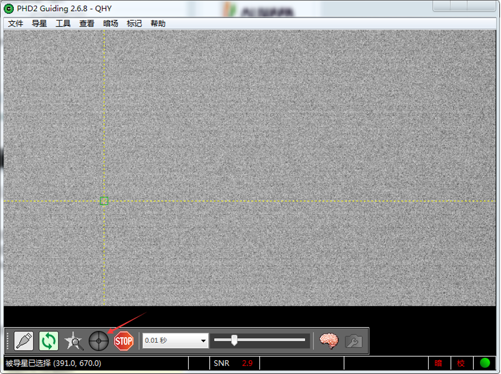
Select a star point on the screen, a green frame appears, and then select to start calibrating the equatorial mount and guide star.
Webcam application and BroadCast Video WDM Drive
QHYCCD BroadCast WDM Camera is a broadcast driver that supports QHYCCD cameras with video broadcast function, which can meet the needs of customers to send video images to other target software. For example, use sharpcap to connect a WDM-enabled camera, and the sharpcap display video image can be sent to other WDM-supported software for display, which is suitable for video online broadcast applications.
Installation:
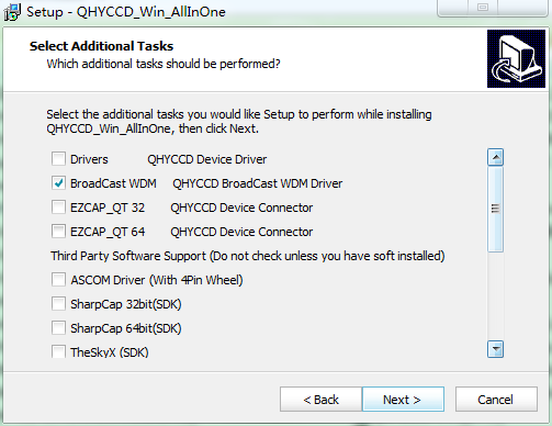
Perform the AllInOne installation and check the BroadCast WDM Camera option.
The installation process is over, right-click the computer to find the device manager, and check that the image device name is QHYCCD BroadCast WDM Camera, which means the installation is successful.
Activate the function:
Usually sharpcap is used to connect the camera as the broadcasting terminal. After connecting the camera, you need to turn on the Enable Live Broadcast switch to broadcast. Common supporting software (ie, broadcast receiver) includes:OBS,UFOCAPTURE, HANDYAVI, QQ video functions, etc.
Note:
Currently only supports Windows system.
Currently, the SDK does not support 16 bits for the time being.
RGB24 mode must be selected for color images, otherwise the image will appear gridded.
Guiding Line
QHY5III Guiding Line Sequence Definition

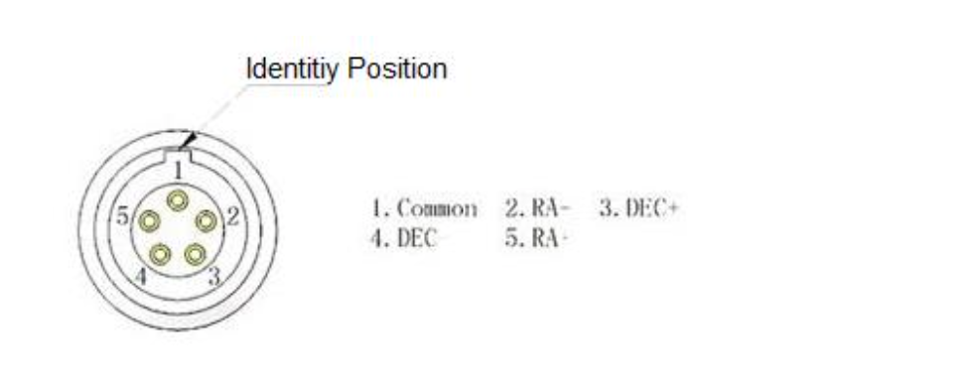
The guide circuit contains an optocoupler isolator. The COMMON pin is generally connected to GND. Usually the four direction pins from the equatorial mount are internally pulled up on the equatorial mount circuit, so when the QHY5III sends out the guide star pulse, the optocoupler pulls it down to realize the output of the guide star command.
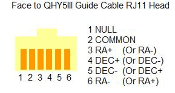
QHY5III Guiding Line RJ11 Crystal Head Wire Sequence
The line sequence is fully compatible with equatorial mounts such as EQ5/EQ6/Aidon/Startron. The order of the pins is (facing the direction of the crystal head)

The line sequence of the socket at the equatorial mount is

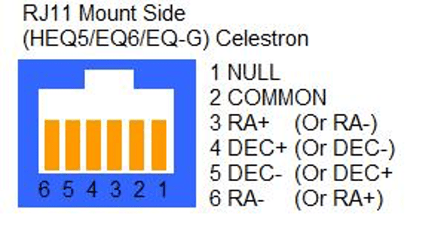
If you use other types of equatorial mounts, please confirm whether the wire sequence is the same as the above.
FAQ
1.QHY5III supports 12-bit or 14-bit images?
QHY5III462C supports 12-bit image output, whether it is 12-bit or 14-bit, it is finally converted into 16-bit output to the computer. (For example, 12 bits are 0-2047, mapped to 0-65535, 14 bits are 0-16383, also mapped to 0-65535)
2. How to get the maximum frame rate?
Because QHY5III series cameras have a very high frame rate and data volume, not all computers can reach the maximum frame rate. Generally I7 quad-core is no problem. However, the CPU occupancy rate will also affect the maximum frame rate, so when using QHY5III, try to close other programs that occupy the CPU and free up the CPU to process the data. If the CPU usage is too high, the program will respond slowly or even crash.
3. How to avoid camera stuck or not smooth?
3.1 Whether the computer or equatorial mount has electric leakage, and the grounding is not good. If there is leakage in the computer or equatorial mount, the leakage current will be transmitted between the camera and the computer via the USB cable, which may easily interfere with the USB transmission signal. Please ensure that the computer or equatorial mount is well grounded and that there are no leakage problems.
3.2 Is the power supply voltage of the USB port sufficient? The voltage output of the USB port of some notebook computers is less than 5V, which will cause insufficient power supply of the camera and easy deadlock. If this is the case, you can use an externally powered USB3.0 HUB to connect the camera.
3.3 Whether the CPU usage is too high. Excessive CPU usage can easily cause images to freeze. You can reduce the USB transfer rate by increasing the value of USB Traffic to solve the problem of high CPU usage, and the image transmission is smoother (but the frame rate will be reduced)
3.4 Whether the USB cable is in good contact. Sometimes there is a bad connection between the USB interface of the computer and the USB interface of the USB cable or the USB interface of the camera, which can cause the USB transmission to be stuck easily. You can confirm this problem by shaking the USB plug slightly to see if the image is stuck during the shaking process. If so, you can replace the USB cable or add a small amount of silicone oil or engine oil to the USB plug, which can effectively solve the problem of poor contact.
3.5 Avoid static electricity. Sometimes the static electricity of the human body can cause the camera to freeze. Especially when the human body touches the camera. Before touching the camera, you can first touch the metal casing of the computer to discharge static electricity, and then contact the camera.
3.6 The front USB port of some computers is connected to the motherboard through a cable inside the computer case, the performance of high-speed signals will be affected, and the power supply capacity may also be reduced. It is easy to cause the USB transmission to get stuck or not smooth. Therefore, avoid using the front USB port, and try to use the rear USB port. The rear USB port is directly routed on the motherboard, and the signal and current can be guaranteed
4. What is the interface of QHY5III to the telescope? How to equip QHY5III with C-mount lens?
The QHY5III462 camera uses a 1.25-inch eyepiece shape design, so it can be added to the 1.25-inch eyepiece without the need for additional interfaces. It also contains the front end of the C-mount, which can be connected to the C-mount lens. Note that this back intercept is slightly less than the standard C back intercept of 17.5 mm. The reason for this design is that a distance of 17.5mm can be achieved through a 1.25-inch spacer. If the distance is designed too close to 17.5mm, then in case it is exceeded, there is no way.
But need to pay attention to choose the C-mount lens according to the chip size. Since the C-mount lens is used, the back intercept is 17.5mm, so it needs to be replaced with a C-mount extension ring. The intercept is extended by 5mm.
5. How to clean the CMOS chip or camera glass window?
Since the surface of SONY I chip is not coated, cleaning is relatively simple. You can unscrew the front of the camera and use lens paper to clean the CMOS chip, or you can use a commercially available SLR camera cleaning kit to clean it.
The glass window of the camera is more likely to be scratched due to the AR coating or infrared cut filter, so it needs to be cleaned carefully.
6. Can QHY5III462C run in FireCapture?
Yes. The latest version of FireCapture already supports QHY5III series cameras. The old version of FircCapture needs to replace the SDK to support. Please go to the QHYCCD website to download the latest version of the SDK and replace it in the FC installation directory.
7. About QHY5III amplifier glow suppression function
Different models of cameras in the QHY5III series have different effects of suppressing the light emission of the amplifier. QHY5III174 and QHY5III224 can see obvious improvement. The amplifier of QHY5III178 itself emits very little light, and QHY5III462 basically has no problem of amplifier lighting.
8. How to solve the problem that the frame rate drops to 0 after the camera runs for a period of time with the DDR mode turned on?
Some users have reported that the camera with DDR module has been running on SharpCap for a period of time and the frame rate has dropped to zero; this problem is caused by the high output rate of the CMOS chip and the slow reception rate of the computer. Once the CMOS sensor starts to work, it will be exposed continuously, and the image will be output again and again without stopping. If the computer suspends USB transmission too frequently due to the operating system, it will cause DDR data to overflow, resulting in continuous generation of bad frames. No image entering the DDR is complete, so the frame rate is zero.
Solution: The first method is to reduce the frame rate of the camera by increasing the value of USB traffic, thereby avoiding the camera stuck. It should be noted that the previous SharpCap patch cannot set the USB traffic value to a large value, so it is necessary to download and install the latest SharpCap patch on the official website. The second method is to turn off DDR mode in SharpCap, but for computers that are not very good, this method may not be effective because of its slow data transmission speed.
HDR Correction of QHY5III585/miniCAM8
FPGA version: 24-12-6 and its later version
SDK version: 24-12-26-12 and its later version
All-in-one version: 24.12.27.10 and its later version
HDR_correction will be on by default. (It is for 16-bit single frames and live, and not available for 8-bit.)
SharpCap version: 4.1.12311 and its later version
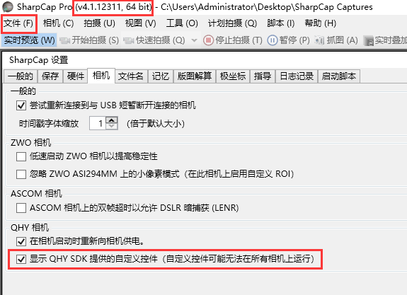
HDR Custom Control in SharpCap: “HDR_correction,” “HDR_L_K,” “HDR_L_b,” and “HDR_showKB”
HDR_L_K: stretch value of the low channel
HDR_L_b: offset value of the low channel
The two values influence the image linearity together.
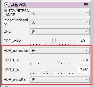 You can manually set values of “HDR_L_k” and “HDR_L_b” by yourself when switching off the “HDR_correction.” But in general we recommend switching it on. Improper values setting will cause issues like image banding.
HDR_showKB: On: values will be shown on the top left of the image; Off: no values shown
Note: In Linearity HDR mode, the Gain and Offset values are set by default and do not need to be adjusted. Any Gain and Offset settings in the software will have no effect.
Appendix: Bayer Sequences of Some Colored Cameras
| Cooled CMOS Camera | Bayer |
| QHY600C/QHY268C/QHY410C/
QHY367Pro/QHY128Pro/QHY294C/ QHY247C/QHY168C/QHY165C/QHY183C/QHY174C |
RGGB |
| QHY533C/QHY178C/QHY290C/QHY224C | GBRG |
| QHY163C | GRBG |
| QHY1920C | BGGR |
| Cooled CCD Camera | |
| QHY8L-C | GBRG |
| QHY10-C | RGGB |
| QHY12-C | BGGR |
| Planetary and Guiding | |
| QHY5III174C | RGGB |
| QHY5III178C | GBRG |
| QHY5III224C | GBRG |
| QHY5III290C | GBRG |
| QHY5III462C | GBRG |
| QHY5III485C | RGGB |
| QHY5L-II-C | GRBG |
| QHY5P-II-C | GBRG |
| QHY5III585C | RGGB |
| QHY5III678C | RGGB |
| QHY5III715C | GBRG |
| QHY5III568C | RGGB |
Appendix: White Balance Adjustment
When SharpCAP starts, it will use the default white balance, which is R:G:B=1:1:1. Therefore, the image you see is greenish (as shown below). Because from the light efficiency curve of the color CMOS chip, the response to green light is the highest. In order to obtain the correct white balance, you need to perform manual white balance adjustment.
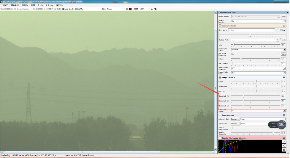
For color cameras, SharpCAP will automatically open the progress bar of the white balance adjustment function, and you can make adjustments.
Since white balance is the ratio of light sensitivity between red and green, and the ratio of light sensitivity between blue and green, you can first fix the green value to 128. Then adjust the red and blue.
For example, after adjustment, blue is 255 and red is 161, and now it looks much better. If you need more blue, because the blue has reached 255 and cannot be adjusted upwards, in this case, you can reduce the green appropriately. Then adjust again. In this way, a larger proportion can be obtained.
As we said before. If you are doing planetary imaging you should set the offset value as low as possible. To make the background close to zero. Then you can easy to get correct color balance. Otherwise it will not easy to get it. The The following image shows the offset is good and you can not get good balance.
The reason is that the Color balance is a ratio of the RGB sensitivity difference. So we use a ratio to multiple the RGB value and get it done. But if there is a bias exist. The ratio will not be correct. For example, the G sensitivity is two times than R.
G=2R In order to get white balance. We multiply a ratio of 2 to R
R’=2R= G so we get R=G
When a bias exist. The bias is a constant add to each pixel. So the image you see is:
R’’=R+bias
G’’=G+bias=2R+bias
Now the ratio R”:G”=(R+bias)/(2R+bias) and it is not equ to 1:2. It shows the bias will effect the true value of the R:G. And the ratio of R:G will arious when the image light changed. It is hardly to correct with a fixed ratio.
But for DSO capture, You should keep the offset above zero and avoid the background is cut off. A background from 1000-5000 is a good value(16bit mode) for DSO imaging.