
Overview
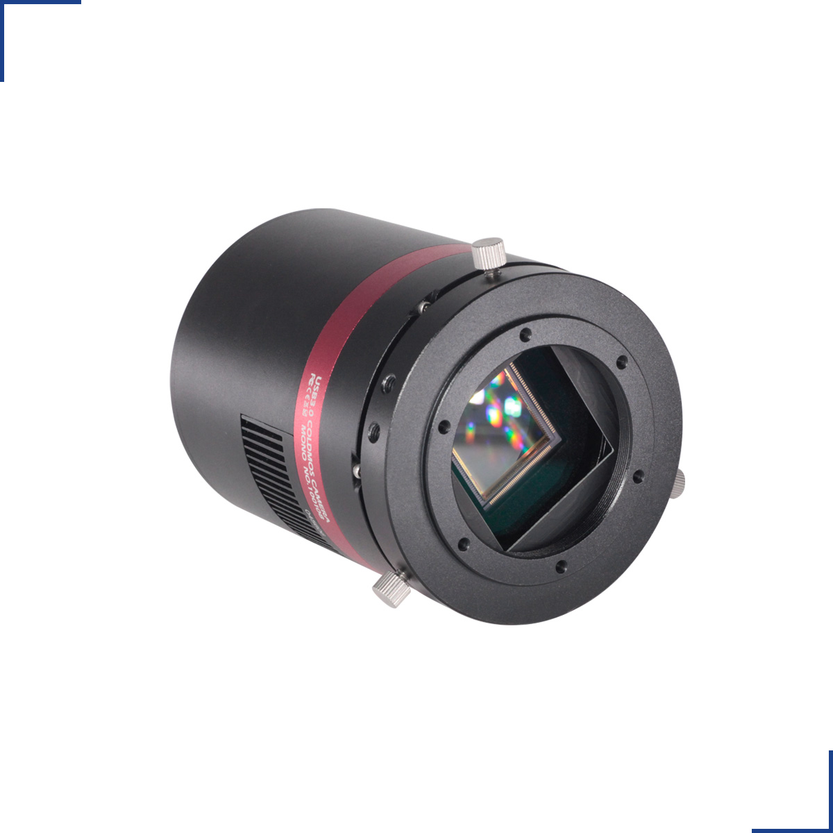
The standard version has 2-stage TE cooling and a USB3.0 interface. The camera has three readout modes: single 12bit high gain channel output, single 12bit low gain channel output. Dual 12bit high gain and low gain output mode. Single channel output is 24FPS at 12-bits. Dual-channel HDR output is 12FPS at 12-bits.
QHY42PRO has the GPS / Trig Signal interface. It can output the precise exposure starting/ending waveform for external measurement. It can also connect with QHYCCD GPS-BOX to measure it. The QHYCCD GPS-BOX will output the timestamp onto the image head of each frame.
Models
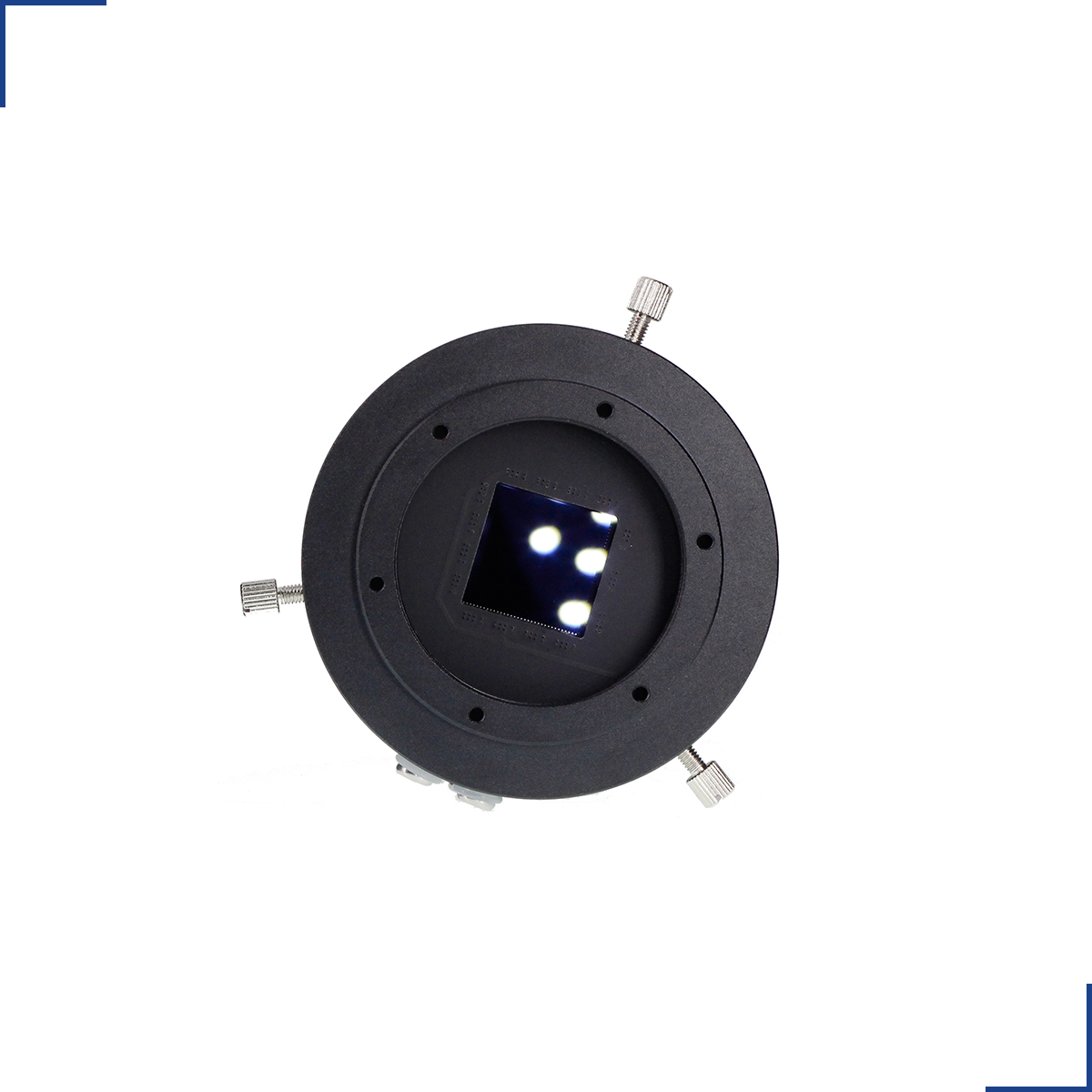
The QHY42PRO is a cooled scientific CMOS camera with extremely low (1.6e-) read noise. The sensor array is 2048 x 2048 with relatively large 11um pixels and 89ke- full well capacity. The QHY42PRO is capable of high frame rates of up to 24FPS at full resolution.
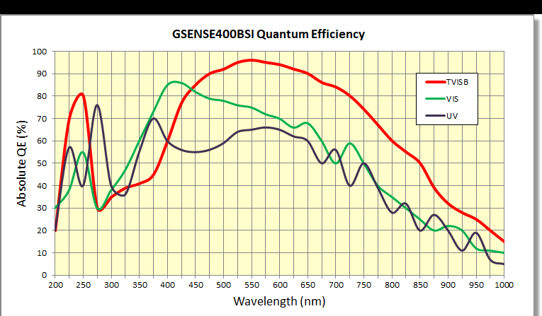
For the BSI version, there are two types of sensor coating. TVISB, VIS. The TVISB is the most popular type and it has the best QE of 95%. The TVISB version has also a high UV QE at 240nm. For UV application, both TVISB and UV are possible to use. You can select it according to the QE curve. VIS version is not so popular and sometimes the sensor factory does not stock. So if you need the VIS version you need to quote QHYCCD for details.
The first version QHY42 is released in early 2018. And now we will release the enhanced version QHY42PRO. The difference between QHY42 and QHY42PRO is that QHY42 only supports the single ADC channel output (which is called STD mode in the datasheet of Gsense400, and 24FPS for 8bit/12bit. While the QHY42PRO supports both STD mode and the dual channel ADC mode (HDR mode). The dual ADC can work together to sample the same pixels. And output two images. One is high gain and another is low gain. Which can enlarge the dynamic of the output data. The QH42PRO HDR mode will output the 4096*2048 image, which consists of two 2048*2048 images. QHY42PRO also supports the remote FPGA upgrade function via a USB port. In the future, if there is any upgrade of the FPGA code, you can upgrade it directly without sending it back to the factory to upgrade.
Specifications
| Model | QHY42Pro |
| Image Sensor | Gpixel GSENSE400 |
| Sensor Type | Mono Only |
| FSI/BSI | Both available |
| Pixel Size | 11μm*11μm |
| Effective Pixels | 4 Megapixels |
| Effective Image Area | 22.5mm*22.5mm |
| Effective Pixel Area | 2048*2048 |
| Total Pixel Area | 2048*2048 |
| A/D | Dual 12-bit A/D (High Gain Channel and Low Gain Channel) |
| Full Well Capacity (1×1, 2×2, 3×3)
|
53ke- |
| Read Noise | LGC Mode:10e- to44e-
HGC Mode1.7e- to 4.2e- |
| Dark Current | 2.2e-/pixel/sec @-20℃ |
| Exposure Time Range | 20μs-300sec |
| Shutter Type | Electronic Rolling Shutter |
| Computer Interface | USB3.0 |
| Filter Wheel Interface
|
4PIN QHYCCD CFW Port |
| Trigger Port | One Hardware Trig-In Socket (RCA type).Opto-isolated |
| Full Frame Rates | USB 3.0:
24FPS@8bit (HDR mode) 12FPS@12bit (HDR mode) 48FPS@8bit (STD mode) 24FPS@12bit (STD mode) |
| ROI Frame Rates
|
USB3.0:
HDR Mode: 1080lines, 24FPS@8bit,12FPS@16bit 768lines, 24FPS@8bit, 12FPS@16bit 480lines, 24FPS@8bit,12FPS@16bit STD Mode: 1080lines, 48FPS@8bit,24FPS@16bit 768lines, 48FPS@8bit, 24FPS@16bit 480lines, 48FPS@8bit,24FPS@16bit |
| Built-in Image Buffer | 128MB DDR2 Memory Buffer |
| Air Cooling System | Dual Stage TEC cooler:
-35℃ below ambient, test temperature +20℃, exposure >1s) |
| Liquid Cooling | |
| Recommended Flow Rates | |
| Anti-Dew Heater | Available |
| Humidity Sensor | Available |
| Firmware/FPGA remote Upgrade | |
| Optic Window Type | QHY42PRO: AR+AR High Quality Multi-Layer Anti-Reflection Coating |
| Back Focal Length | 17.5mm |
| Adapters | Support 2-inch, M54, M48, Nikon/Canon DSLR Lens, etc. (Combined with adapters ) |
| Weight | 735g |
| Power | 27W/100%
12W/50% 4W/0% |
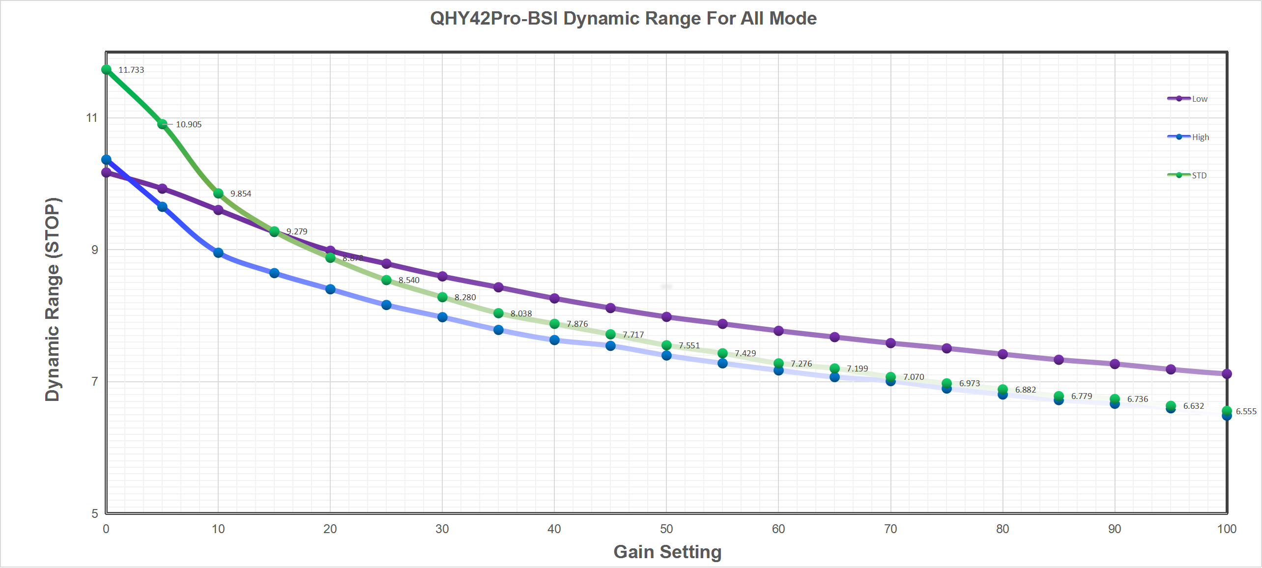
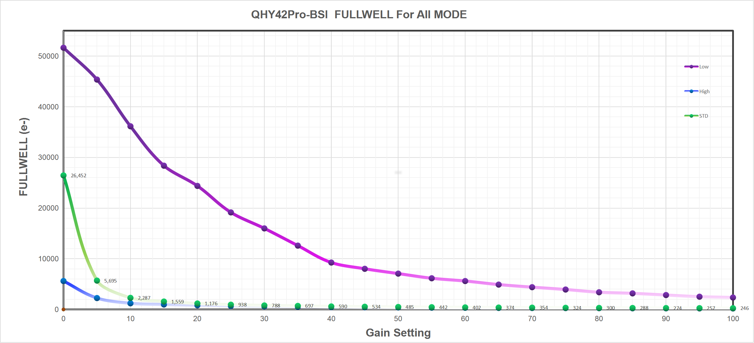
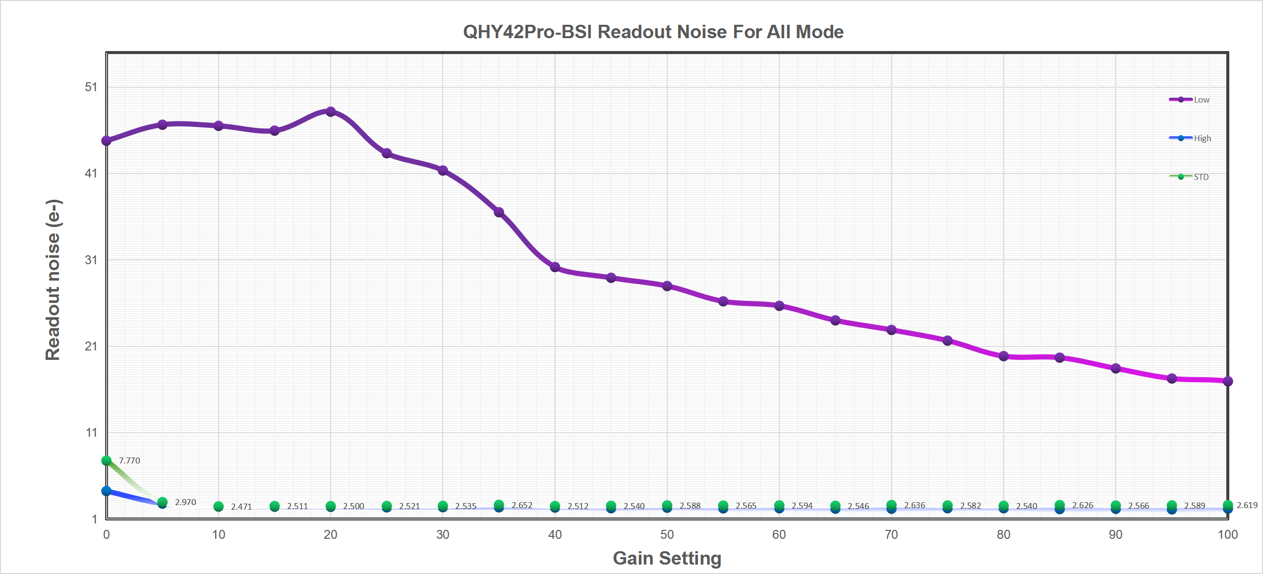
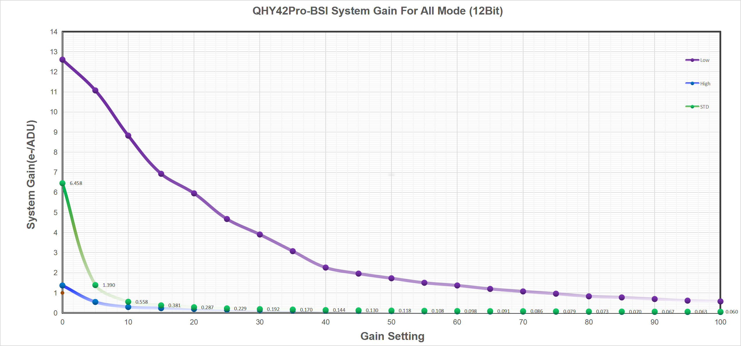
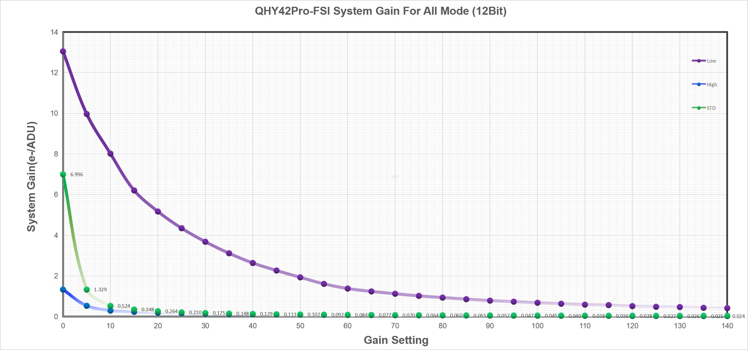
Curves
QHY42Pro-BSI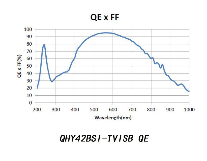
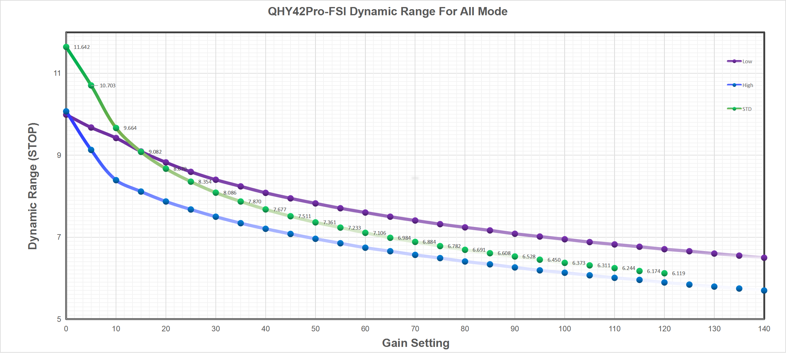
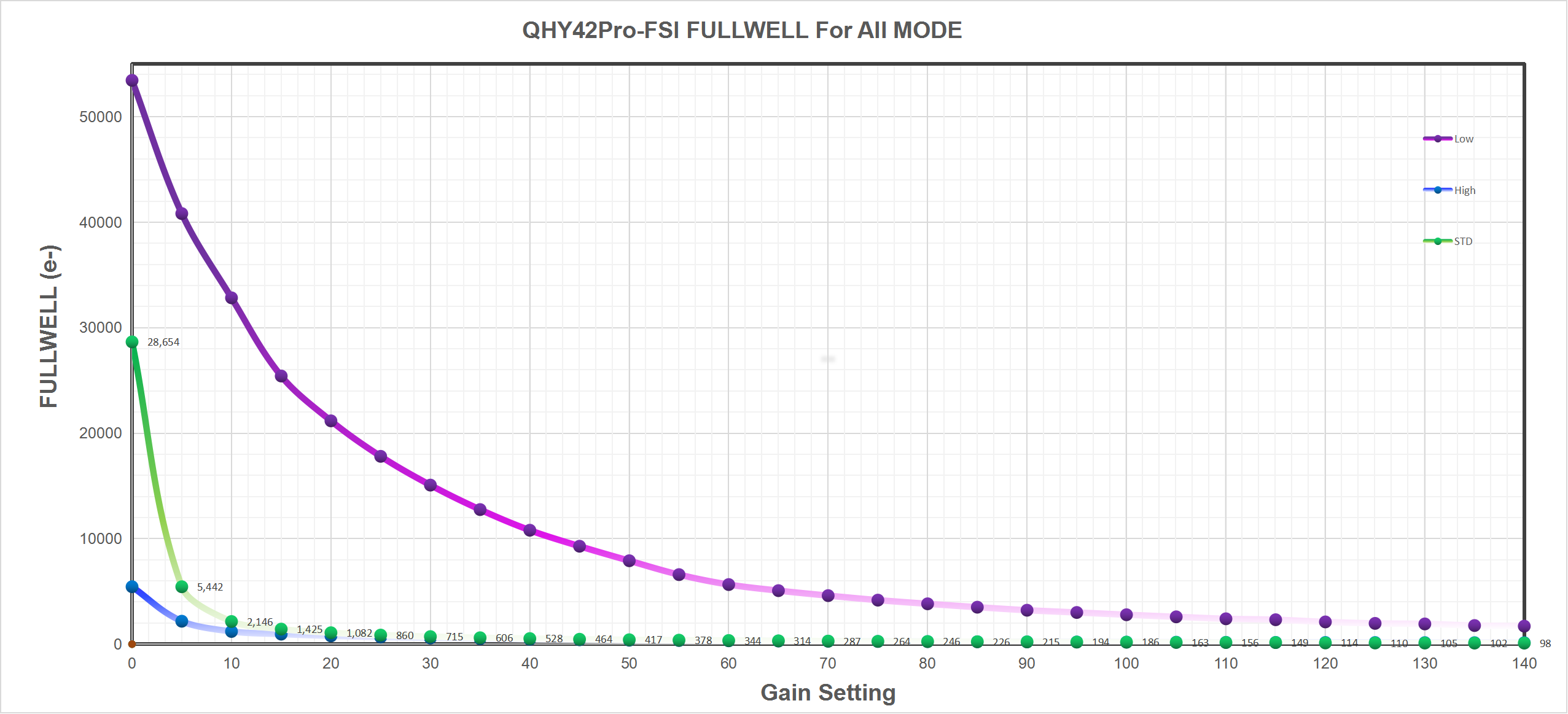
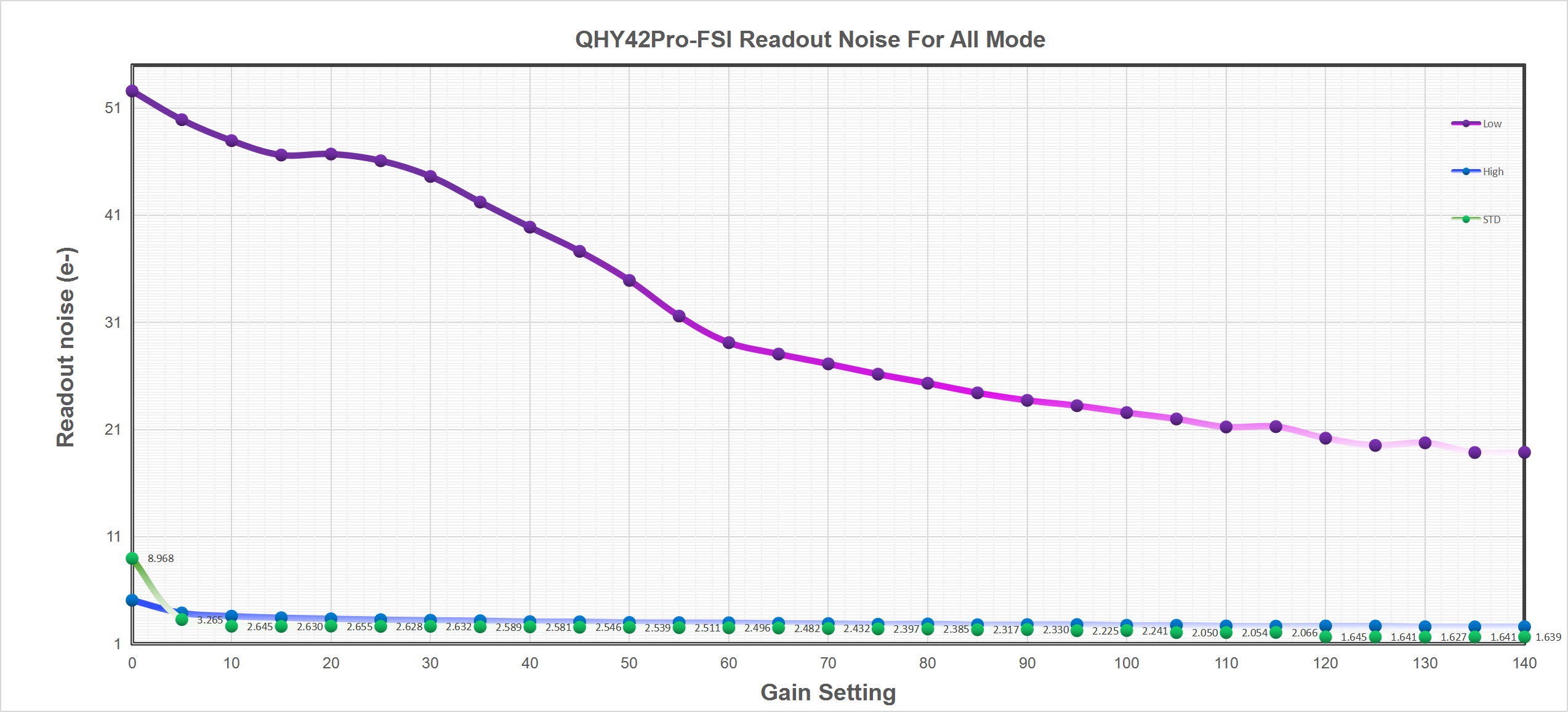
QHY42Pro-FSI
Camera Information
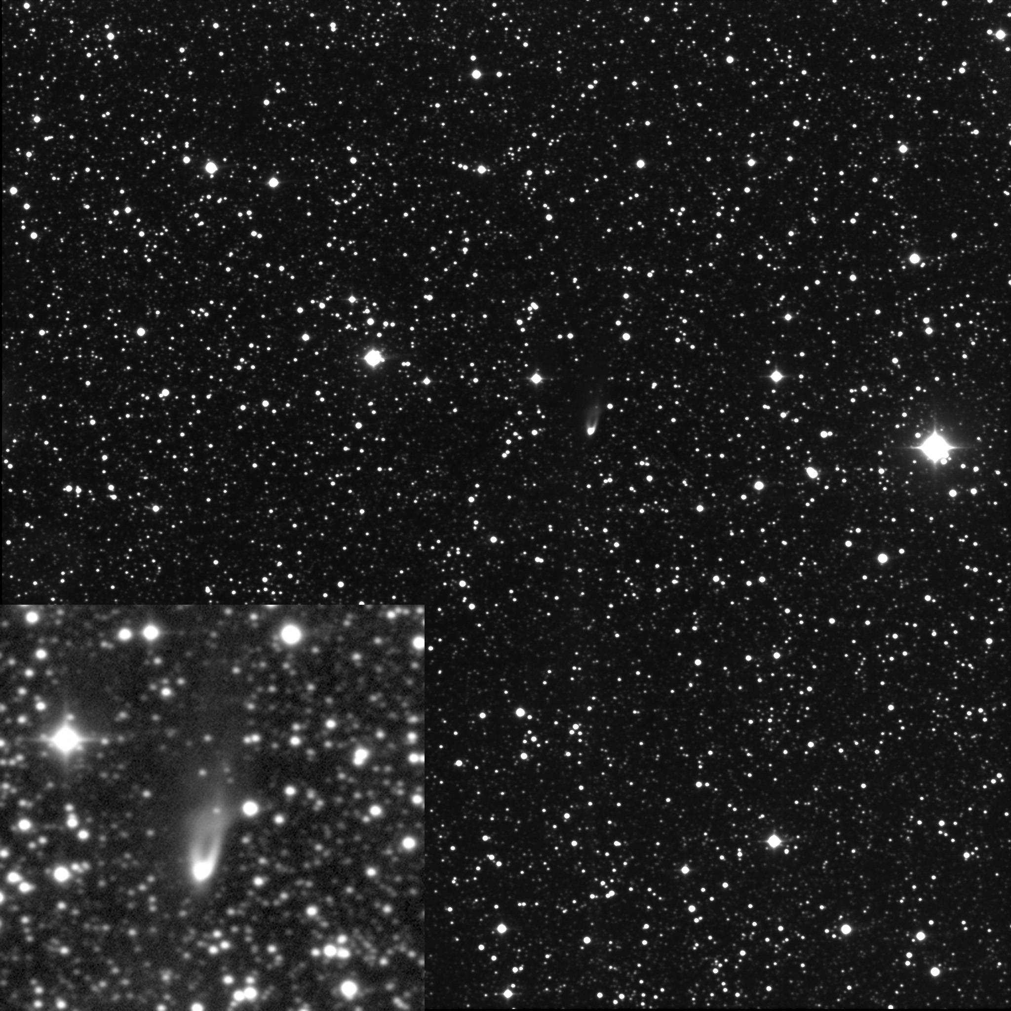
QHY42 Test Image by Dr.Martin Miller
The test results shows the high sensitivity of QHY42, especially in Ha wavelength, and the ultra low readout noise. results the high SNR image in short exposure time. Dr.Martin Miller says QHY42 has great potential in professional astronomy imaging. See all of the test image and the parameter at http://avvamhl.xobor.de/g90-Test-der-Scientific-QHY-CMOS-Kamera-p2.html
Der kometarische Nebel ist ein Reflexionsnebel, der sich durch den Aussfluss eine jungen Stern gebildet hat und von diesem angeleuchtet wird. 62 x 30 Sekunden, Gain 2, Offset 20, T= -22°C, 16″Mak, Sternwarte Hö, MartinMiller
Brief User Guide
Install “All-In-One” Driver&SDK Pack
Before Start: Input Voltage Requirements
The camera requires an input voltage between 11V and 13.8V. If the input voltage is too low the camera will stop functioning or it may reboot when the TEC power percent is high, causing a drain on the power. Therefore, please make sure the input voltage arrived to the camera is adequate. 12V is the best but please note that a 12V cable that is very long or a cable with small conductor wire may exhibit enough resistance to cause a voltage drop between the power supply and the camera. The formular is: V(drop) = I * R (cable). It is advised that a very long 12V power cable not be used. It is better to place the 12V AC adapter closer to the camera.
First connect the 12V power supply, then connect the camera to your computer via the USB3.0 cable. Make sure the camera is plugged in before connecting the camera to the computer, otherwise the camera will not be recognized. When you connect the camera for the first time, the system discovers the new device and looks for drivers for it. You can skip the online search step by clicking “Skip obtaining the driver software from Windows Update” and the computer will automatically find the driver locally and install it. If we take the 5IIISeries driver as an example (shown below), after the driver software is successfully installed, you will see QHY5IIISeries_IO in the device manager.
Please note that the input voltage cannot be lower than 11.5v, otherwise the device will be unable to work normally.
Install "All-In-One" System Pack
All-in-one Pack supports most QHYCCD models only except PoleMaster and several discontinued CCD cameras.
Download Page: https://www.qhyccd.com/download/
Video Tutorial: https://www.youtube.com/embed/mZDxIK0GZRc?start=1
- Since most of the contents of All-in-one package are plug-ins that support third-party software, the third-party capturing software that you want to use must be installed before the All-in-one package. Otherwise the program will report an error.
- ALL-IN-ONE Pack contains:
- System Driver, which is necessary for the camera operation and must be installed.
- WDM Broadcast Driver, which can provide a live signal to Obs and other live software, you can install it if you have such needs like opeing a live show.
- EZCAP_QT , which is developed by QHYCCD and can be used in QHY devices tests, and management of updates. So even if you won’t use EZCAP_QT for capturing, we suggest you install it.
- Ascom driver, which is necessary for the camera used in Ascom (the latest version of Ascom is 6.6).
- The two sorts of Ascom CFW Drivers correspond to two methods of controling the filter wheel: USB control and camera serial control. It is recommended that both drivers should be installed if you have a filter wheel.
- CP210X_VCP is a serial driver. Some computers come with the driver, but the computer without the driver may be failed of controling the filter wheel.
- SDKs for Third-party Software: Just pick and install the corresponding SDK according to the software you want to use. Don’t forget to check whether the software you are using is 32-bit or 64-bit and select the right SDKs.
- SHARPCAP is also included in the pack, you can choose 32-bit or 64-bit to install. This is authorized by SHARPCAP.
- QT LIB is a plug-in to ensure that 64-bit software can exeuate normally on some computers with poor compatibility.
- Difference between Stable version and Beta Version: Beta version is the latest version, which gives priority to support for the latest products (the stable version may not be compatible with those yet), and has some of the latest optimized ,but experimental features. The stable version is older than the beta version but more stable, so it is recommended for beginners who are not using the latest products.
- Don’t let the camera connect to the computer during the All-in-one pack installation process; connect it to the computer after all the installation is complete.
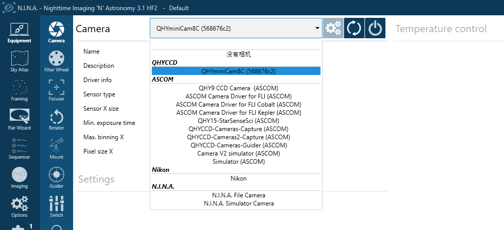
Connect DSO Imaging Software (e.g. NINA)
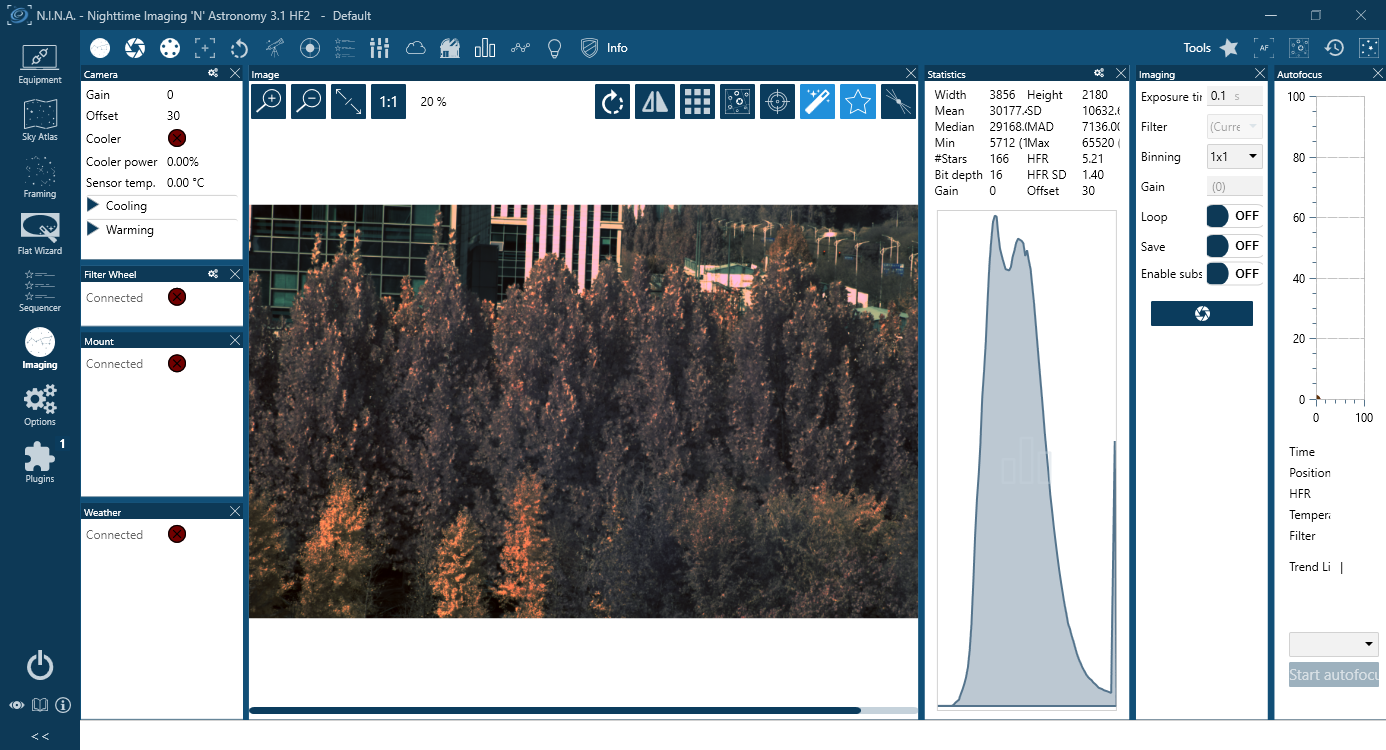
Before using software, make sure you have connected the cooling camera to the 12V power supply and connected it to the computer with a USB3.0 data cable. If it’s an uncooled camera, 12V power is not needed. We recommend 64-bit Software, like SharpCAP x64 , N.I.N.A x64. etc., especially when you’re using 16bit cameras.
NINA supports direct connection via the QHY plugin as well as connection through the ASCOM driver. The following instructions assume a direct connection using the QHY plugin.
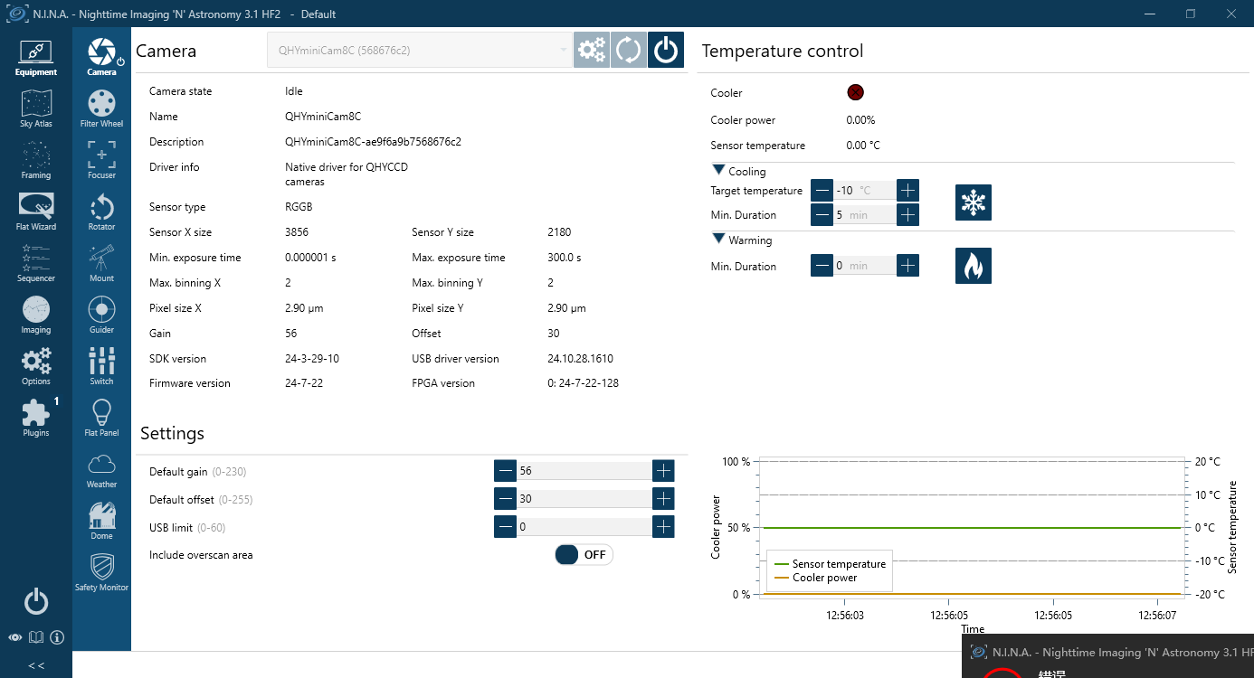
Set the Target temperature.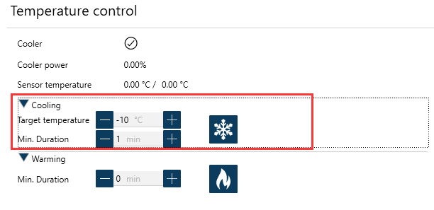
Set exposure time and start the shooting.
Connect Planetary Imaging Software (e.g. SharpCap)
The instructions below are based on SharpCap 3.1
- Launch SharpCap.
Click Camera in the menu bar and select your camera.
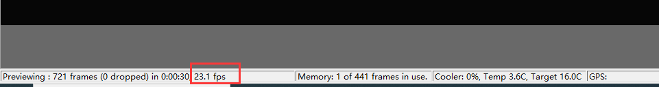
If the software and drivers mentioned above have been installed correctly, the image will appear automatically. And the frame rate can also be seen in the lower-left corner of the software window, as shown below.
- Main Interface Functions:
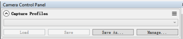
Capture Profiles
Preset management.
After SharpCap is restarted, the default settings are restored. If you frequently use one or more specific parameter configurations, you can adjust the parameters as needed and then click Save to store them as a preset. The preset can be directly recalled the next time you open the software.
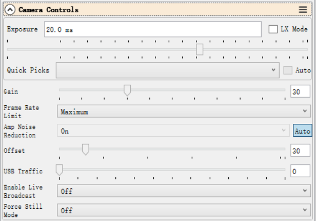
Exposure
Sets the exposure duration. When LX Mode is enabled, the single-frame exposure time can be extended to longer values.
Gain
Equivalent to the ISO setting on a standard digital camera. Higher gain values result in higher sensitivity.
Frame Rate Limit
Limits the maximum frame rate. By default, no limit is applied. Users can set the limit manually if needed.
Offset
Adjusts the bias level. Even when the camera is completely covered, the image may not appear perfectly black. By adjusting the offset value, a more optimal dark frame can be achieved. The Histogram can be used to verify the adjustment.
USB Traffic
Controls the data transfer speed (frame rate). When set to 0, the camera operates at its maximum frame rate.
Enable Broadcast Mode
Enables the broadcast driver. For detailed usage instructions, please refer to the documentation available on the download page.
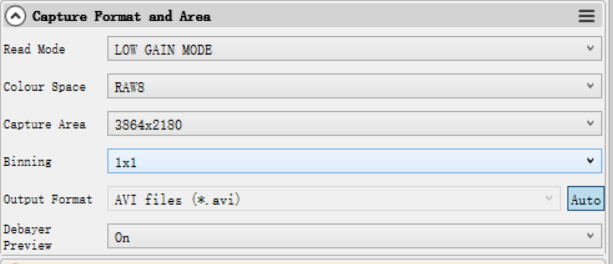
Read Mode
Some camera models support high-gain and low-gain readout modes.
Color Space
Select the output format.
Raw8 / Raw16 are 8-bit or 16-bit formats. Images and videos saved in Raw8 or Raw16 format will be monochrome, even when using a color sensor. Color information must be restored through debayering during post-processing.
RGB24 is a non-RAW format that outputs color images directly, but requires more storage space.
Capture Area
Select the resolution used for image capture.
Binning
Enable pixel binning for image capture.
Output Format
Select the output file format.
Debayer Preview
When this function is enabled, the live preview will be displayed in color even if a RAW format is selected. Please note that the saved images will still be monochrome.
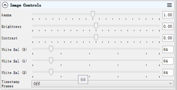
Gamma, Brightness, Contrast
Under normal operating conditions, we recommend leaving these settings unchanged.
White Balance (R/G/B)
This function is used for white balance calibration on color cameras. For detailed calibration instructions, please refer to the corresponding section on the color camera page.
This function is not required for monochrome cameras.
Histogram
The histogram is an important image reference tool. It can be used to check whether the white balance is set correctly, whether the offset value is appropriate, and whether the image is overexposed.
Its operating principle is the same as that of the histogram used in standard DSLR cameras.

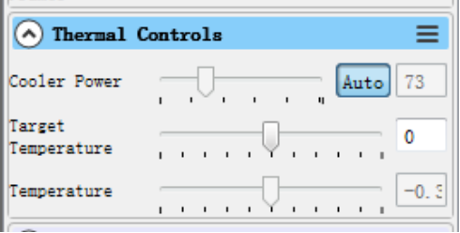
Thermal Controls
After the cooled camera is connected to a 12 V power supply, the temperature control circuit will be activated. You can control the CMOS sensor temperature by adjusting the settings shown below.
There are two main methods for temperature control:
Adjusting the cooler power
Setting a target temperature
If you wish to control the CMOS temperature by setting a target temperature, first click “Auto”, and then use the slider to set the desired target temperature.
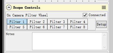
Scope Control: for filter wheel control
Select the corresponding filter wheel slot to control the rotation.
Note: The software must be started after the filter wheel has completed its rotation and returned to the home position; otherwise, the position will not be displayed correctly.
Using Ascom
QHY devices can operate with many software applications that support the ASCOM platform. MAXIM DL is used as an example below.
First, make sure that both the ASCOM platform and the QHY ASCOM driver have been successfully installed. Launch MAXIM DL and follow the instructions shown in the figure below to complete the setup.
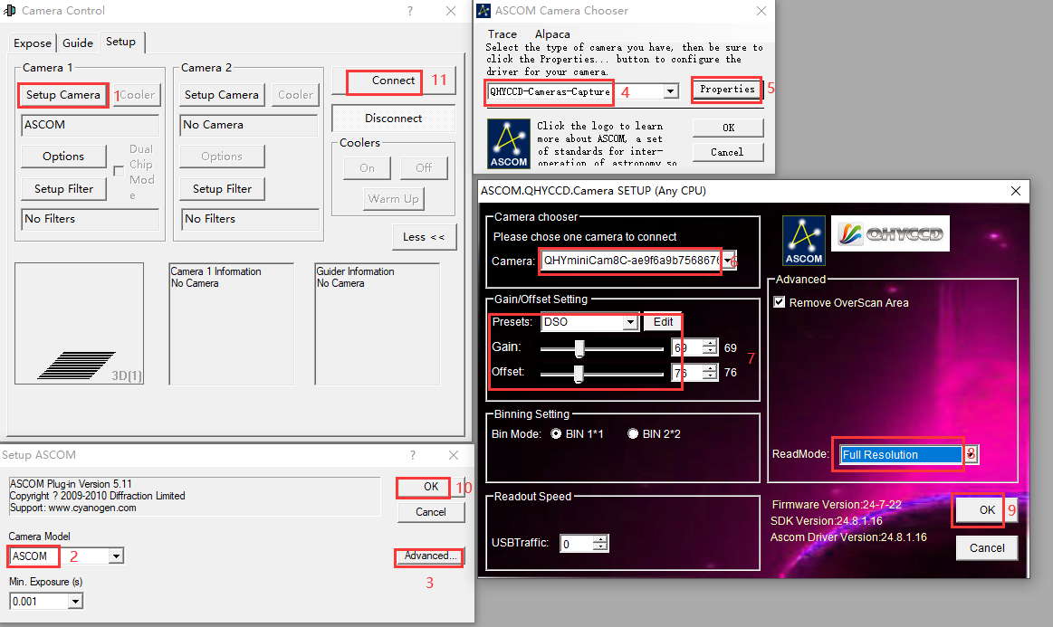
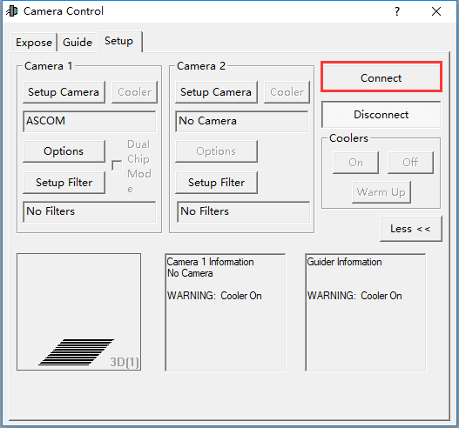
Click “Connect”
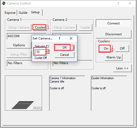
Set the cooling temperature.
Using EZCAP
EZCAP_QT is software developed by QHYCCD. For QHYCCD cameras, it provides basic image capture functions.
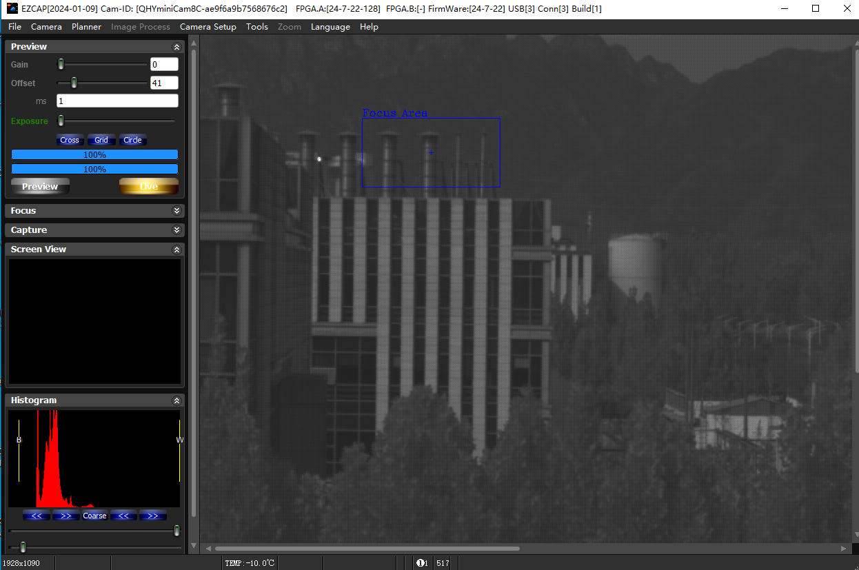
Install the EZCAP_QT software and connect the camera to your computer using a USB 3.0 cable. Launch EZCAP_QT, then click “Connect” under Menu → Camera.
If the camera is successfully connected, the EZCAP_QT title bar will display the camera firmware version and camera ID, as shown in the figure below.

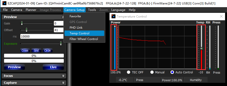
In Camera Setup, click Temp Control to set the CMOS sensor temperature.
You can enable Auto to define a target temperature. For example, here we set the target temperature to –10 °C. The CMOS sensor temperature will quickly drop to the target value, typically within 2–3 minutes.
To disable cooling, select Stop. If you prefer to control the cooling power without setting a target temperature, you can manually set the cooling power as a percentage.
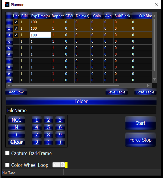
In EZCAP_QT, there is an Image Task Planner for sequence imaging.
Check Use to enable the task.
Set the following parameters:
Bin
ExpTime – exposure time
Repeat – number of frames
CFW – filter wheel position
Gain – gain value for the sequence
Click Folder to set the save path. (It is recommended to avoid special characters in the path and use English letters.)
Click Start to begin the sequence capture, and Force Stop to close the current task.
Camera Maintenance
Drying the camera CMOS chamber
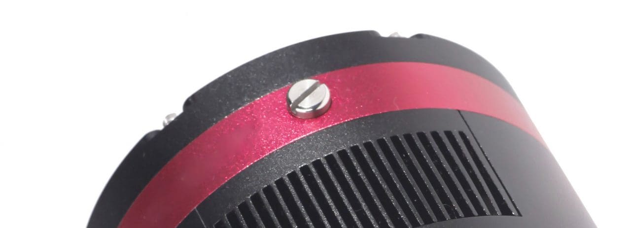
- There are holes in the two sides of the camera near the front plate that is normally plugged by a screw with an o-ring. If there’s moisture in the CMOS chamber that causes fog, you can connect the desiccant tube to this hole for drying. There would better be some cotton inside to prevent the desiccants from entering the CMOS chamber.
 Please note that you may need to prepare desiccants yourself, because for most countries and regions desiccants are prohibited by air transport. Since QHY always deliver your goods by air, sorry that we can’t provide desiccants for you directly.
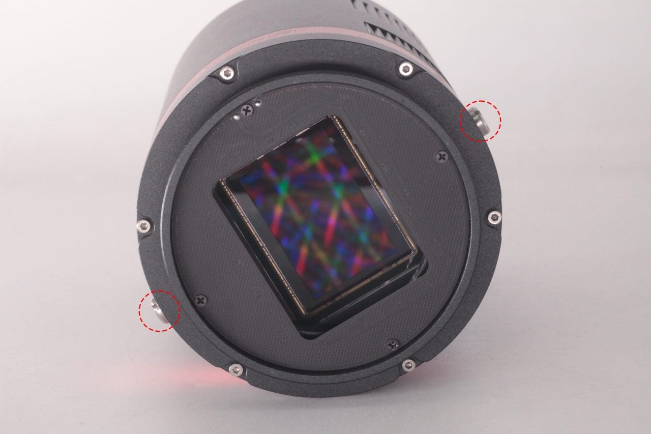
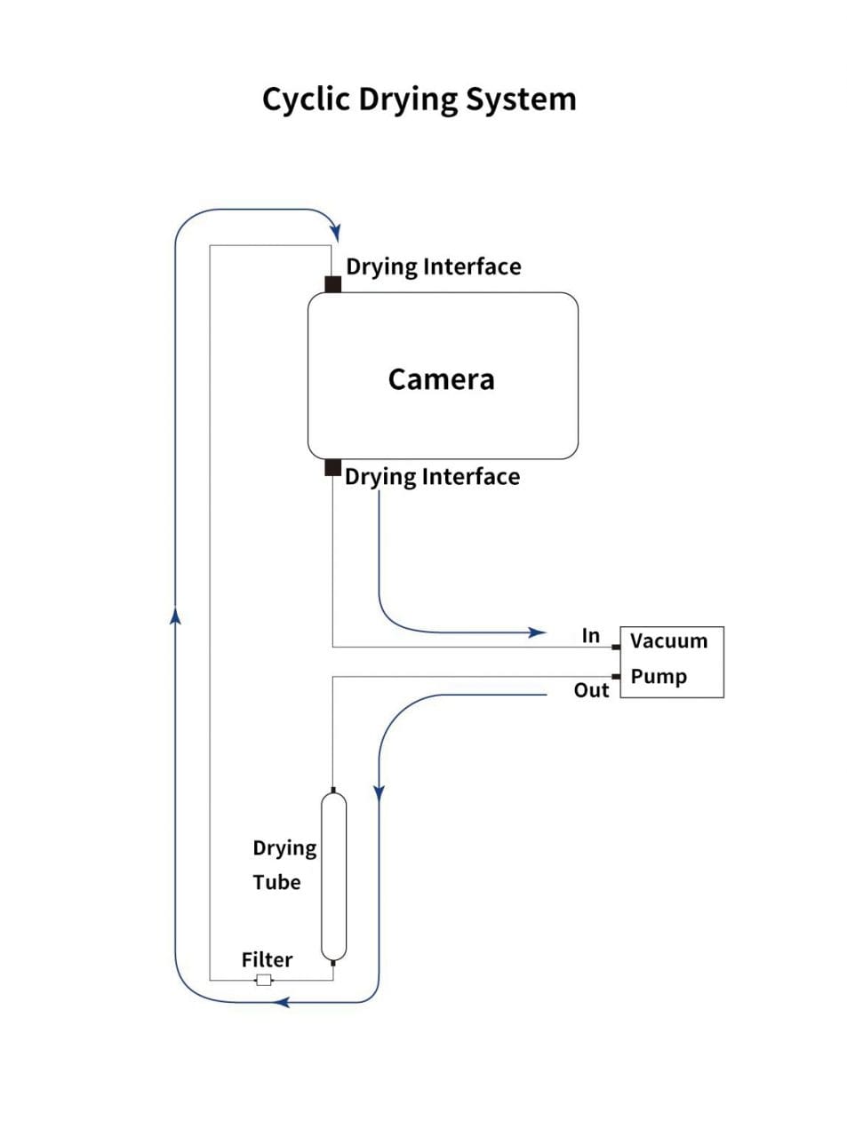
 - Cyclic Drying: The front end of the camera body is equipped with two drying interfaces with M5 threads, which are used in conjunction with drying tubes and circulation pumps for drying treatment inside the sensor chamber. The position of the drying interface is indicated by the red circle in the figure below (take the QHY600 as an example):Under the vacuum pump, the gas inside the sensor chamber is drawn out through one drying interface, enters the drying tube, and then undergoes filtration. It is then reintroduced into the camera through the other drying interface, circulating back and forth for drying.
Note:1.Do not reverse the order of the intake and exhaust ports
2.Before circulating drying, it is necessary to turn off the refrigerator, and then turn on circulating drying after the temperature returns to normal temperature. Only by following this step can the water vapor in the sealed chamber be effectively removed. If the cooler is turned on, the cooler inside the camera will absorb water vapor, causing more water vapor to condense inside the camera instead of being absorbed by the desiccant.
Cleaning the CMOS sensor and optical window
If you find dust on the CMOS sensor, you can first unscrew the front plate of the cam and then clean the CMOS sensor with a cleaning kit for SLR camera sensors. Because the CMOS sensor has an AR (or AR/IR) coating, you need to be careful when cleaning. This coating can scratch easily so you should not use excessive force when cleaning dust from its surface.
Preventing fogging of the CMOS chamber
All QHY cooling cameras have built-in heating plates to prevent fogging. However, If the ambient humidity is very high, the optical window of the CMOS chamber may have condensation issues. Then try the following:
1. Avoid directing the camera towards the ground. The density of cold air is greater than of hot air. If the camera is facing down, cold air will be more accessible to the glass, causing it to cool down and fog.
2. Slightly increase the temperature of the CMOS sensor .
3. Check if the heating plate is normally working. If the heating plate is not working, the glass will be very easy to fog, the temperature of the heating plate can reach 65-70 °C in the environment of 25 °C. If it does not reach this, the heating plate may be damaged. Please contact us for maintenance.
TE Cooler Maintenance
Please avoid thermal shock during use. Thermal shock refers to the internal stress that the TE cooler has to withstand due to the thermal expansion and contraction when the temperature of the TEC suddenly rises or falls. Thermal shock may shorten the life of the TEC or even damage it.
Therefore, when you start using the TEC to adjust the CMOS temperature, you should gradually increase the TEC power rather than turning the TEC to maximum power. If the power of the TEC is high before disconnecting the power supply, you should also gradually reduce the power of the TEC and then disconnect the power supply.
Advanced Features
QHY42PRO Adanced Shutter Measurement
The QHY42PRO support the advanced Trig Out signal. Support both QHYCCD 4PIN , 5PIN , 6PIN GPIO port defination. These defination can be switched with the REG39. And there is a TrigOut output pulse enable resigster REG142, This regsiter is used to disable the output signal to avoid some unexpected signal output, like during the camera initialize, and mode change.
To active the QHY42PRO advanced Trig Out function, you need to upgrade the two FPGA firmware in the camera with:
FPGA_V20191118
MAX10_V20191120
REG39[3:0] GPIO Mode Switch Register.
0:I2C controlled GPIO signal output
1:QHYCCD GPS_BOX (6PIN)
2:5PIN
3: 4PIN
4: Multiple Camera Sync-Working mode . Master
5: Multiple Camera Sync-Working mode . Slave
6 to 15: Undefined
REG142 TrigEnable Control Resgister
0: Disable the Output pulse
1: Enable the Output pulse.
About 5PIN PORT
5PIN cable color define
|
PIN NUMBER
|
COLOR
|
SIGNAL NAME
|
|
1
|
BLACK
|
Shutter Messurement
|
|
2
|
WHITE
|
N.A
|
|
3
|
GREY
|
LinePeriod
|
|
4
|
RED
|
TRIGOUT
|
|
5
|
BROWN
|
GND
|
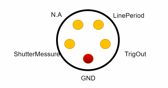
5PIN socket define (Face to the camera port side) and please note there is a red mark point.
Important Note:
The four IO in this port is the directly digital output , no opto-isolated. The IO standard is the 2.5V Level. High level is 2.5V. Low level is 0V. The 5pin is connected with the camera hardware with a ESD protec component. For the 5PIN I/O config, the four IO is directly output only. Please do not input any signal into it or connect it any voltage. Even it has ESD protect. But please take it carefully to avoid the static damage.
CAUTION:
Don’t use the original open-drain connect method for it !!! Any voltage applied in these IO exceed 2.5V may damge the camera!!!!!
ShuterMessure Waveform
The shutterMessure waveform is the high precise waveform to indicate the begin/end exposure. Please note for QHY42PRO, it is the begin/end exposure of the ROW 0. The rising edge is the exposure beginning and the falling edge is the exposure ending. The width is the exposure time. You can connect the GPS messurement device to messure it directly. This waveform output support both Live video mode, Single mode and Burst mode
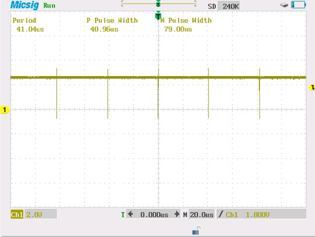
LinePeriod
For rolling shutter CMOS, you need to get to know the Line Period then you can calcuate other rows exposure time beginning and ending. With this formual:
The t(begin2) is the row 2 beginning time. So :
t(begin3)=t(begin2)+LinePeriod
t(begin4)=t(begin2)+2*LinePeriod
……….
The same as the t(end2)
The LinePeriod is a fixed value for all QHY42PRO cameras. So you only need to test one time.And write down of it. Please note in different SPEED setting . The LinePeriod will be not the same. Only SPEED setting will effect it. You can messure each SPEED setting and write down of it.
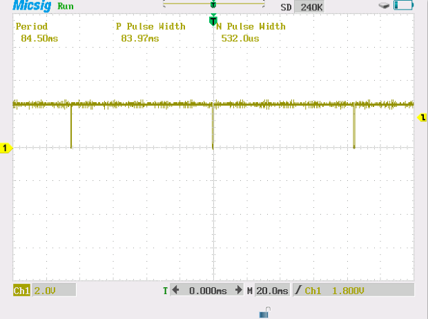
TrigOut (High Speed)
TrigOut singal is for normal messurement, not for high precise messurement. The TrigOut signal is the vertical Sync signal in the camera. It is a short pulse (the pulse is low level) . The falling edge of the TrigOut is close to end exposure of row 0 and the rising edge is nothing. This waveform output support both Live video mode, Single mode and Burst mode.
About SMA Trig In, Trig Out Port.
There is two SMA port on the camera. Trig In and Trig Out. Trig In is to input a hardware signal to trig the camera begin a capture in hardware. Trig Out is output the TrigOut signal or Shutter Measure signal or other signal. These two port is opto-isolated port and it is low speed port (due to the slow rising/falling edge of opto-isolater). But it has better ESD protect for the camera and suitable for longer cable.
REG39 BIT[7:6] Mode Switch Bit for TrigIn Port
0: ShutterMeasure Waveform Output
1: TrigOut (Vertical Sync) Output
2: Undefined
3: Undefined
REG39 BIT[5:4] Mode Switch Bit for TrigOut Port
0: Undefined
1: Undefined
2: Undefined
3: Undefined
Since the structure of the opto-isolator , the TrigOut port need have a pull up resistor to pull it up to a voltage. For example, 5kohm to connect to the 3.3V-12V.
For TrigIn, you can input a voltage with a current limitation resistor in series with it.
Sample WaveForm
LinePeriod Waveform in 5PIN port
TrigOut waveform in 5PIN Port
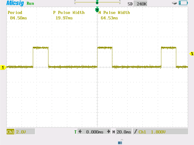
Shutter Measure Waveform in 5PIN PORT @ exposure time set to 20.0ms
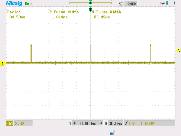
Shutter Measure Waveform in 5PIN PORT @ exposure time set to 1.0ms
Reference Papers / Documents
Transit Measures with QHY42 Camera by Bruno Fontaine
Transit Measures with QHY 42 Camera
QHY42 Test Image by Dr.Martin Miller
The test results shows the high sensitivity of QHY42, especially in Ha wavelength, and the ultra low readout noise. results the high SNR image in short exposure time. Dr.Martin Miller says QHY42 has great potential in professional astronomy imaging. See all of the test image and the parameter at
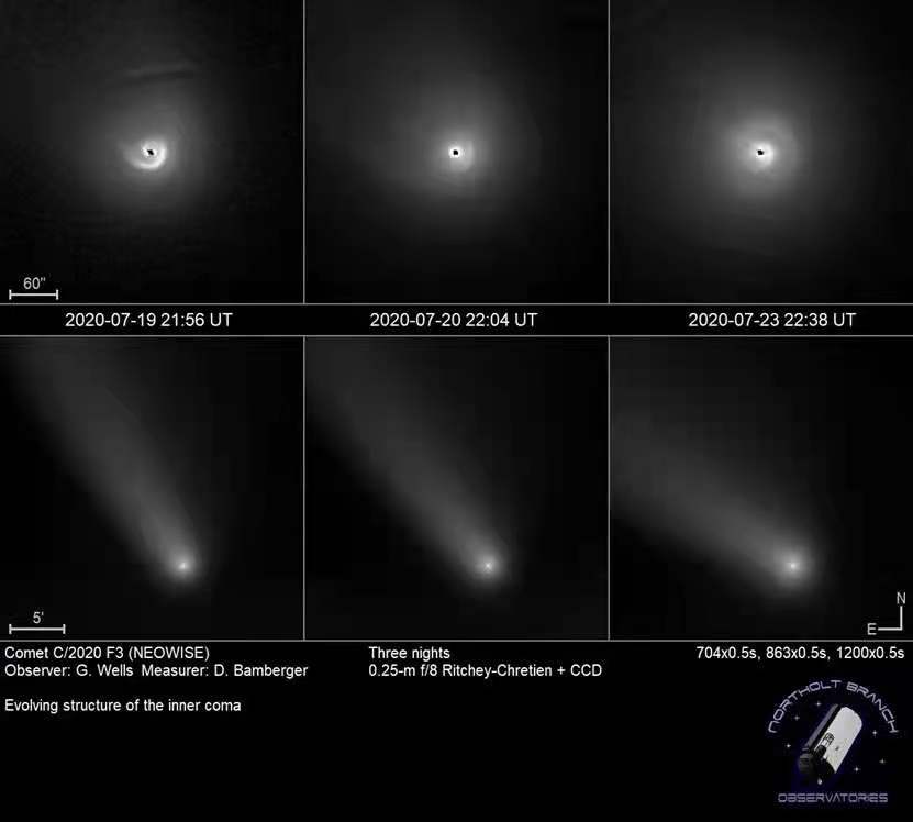
QHY42 User: Northolt Branch Observatories
https://www.facebook.com/NBObservatories
QHY42 User:Irydeo Astronomical Observatory (MPC Z41)
https://www.facebook.com/irydeoobs.obs
User Interview
Space Exploration of Northolt Branch Obs
QHYCCD BURST Mode
QHYCCD BURST Mode
Added functions related to BURST mode in SDK. Currently, cameras that support Burst function include QHY600, QHY411, QHY461, QHY268, QHY6060, QHY4040, QHY4040PRO, QHY2020, QHY42PRO, QHY183A
This mode is a sub-mode of continuous mode. This function can only be used in continuous mode. When this function is enabled, the camera will stop outputting image data, and the software frame rate will be reduced to 0. At this time, send relevant commands to the camera, and the camera will Output the image data with the specified frame number according to the settings, for example, set Start End to 1 6, the camera will output the image data with the frame number 2 3 4 5 when receiving the command.
Note:
1. When using Burst mode in fiber mode, the first Burst shot will be one less. For example, if the start end is set to 1 6, the output of 2 3 4 5 is normal, but in fact, only 3 4 will be output during the first burst shot. 5, 2 will not be received, the second and subsequent shots can normally obtain Burst images 2 3 4 5. This problem will be fixed later.
2. QHY2020, QHY4040 found that the frame number that came out when the exposure time was short is [start+1,end-1] but the one that came out under long exposure was [start+2,end]
3. When the camera is just connected, if the set end value is relatively large, the camera will directly output the picture after entering the burst mode. Therefore, it is necessary to set the camera to enter the IDLE state and then set the start end and related burst operations.
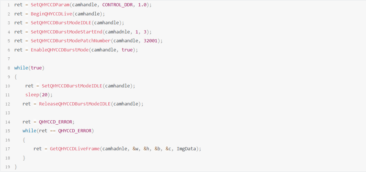
The following is the usage of Burst mode related functions:
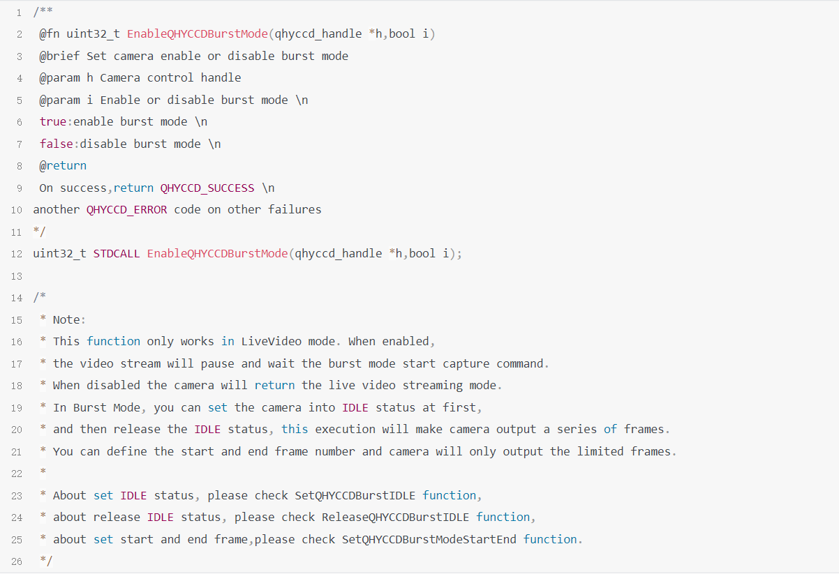
1.EnableQHYCCDBurstMode
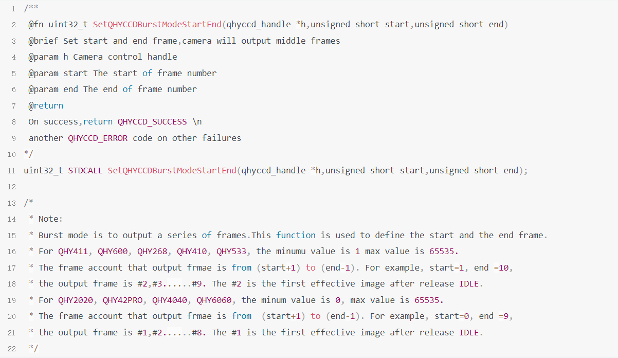
2.SetQHYCCDBurstModeStartEnd
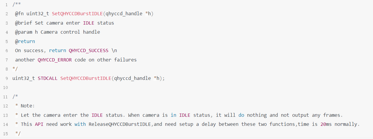
3.SetQHYCCDBurstIDLE
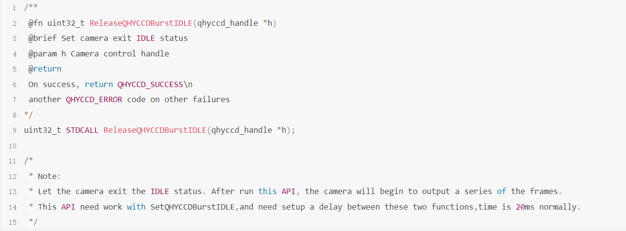
4.ReleaseQHYCCDBurstIDLE
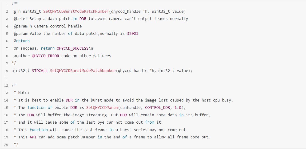
5.SetQHYCCDBurstModePatchNumber
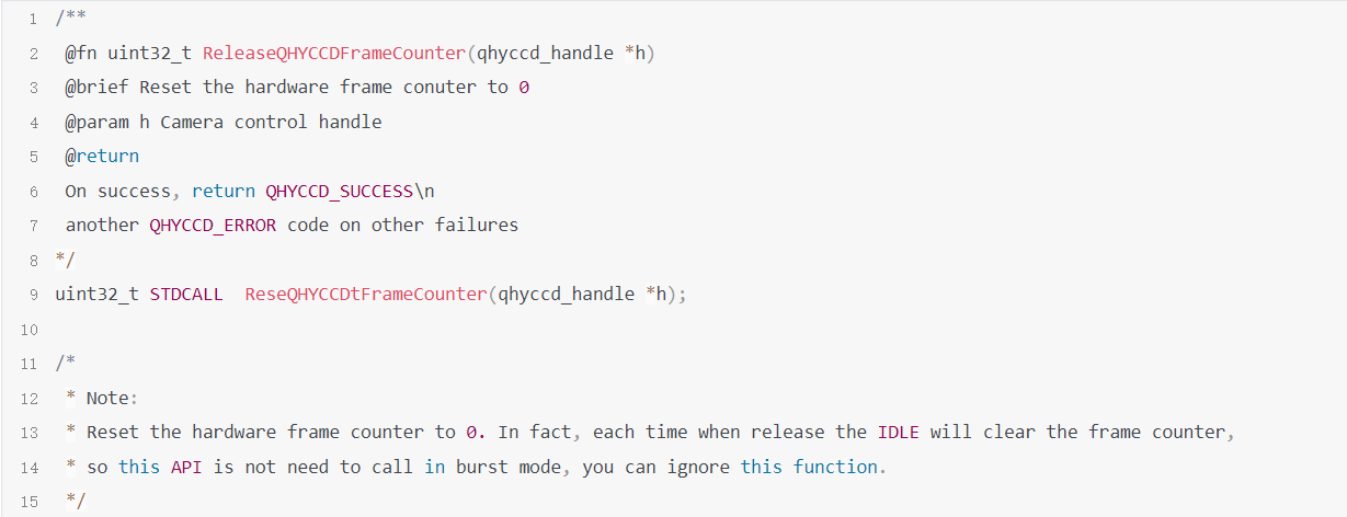
6.ReseQHYCCDtFrameCounter
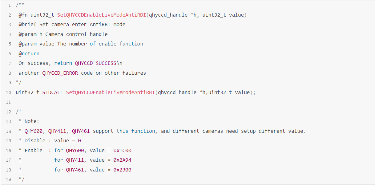
7.SetQHYCCDEnableLiveModeAntiRBI
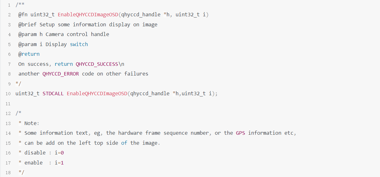
8.EnableQHYCCDImageOSD
Sample Code