
Overview
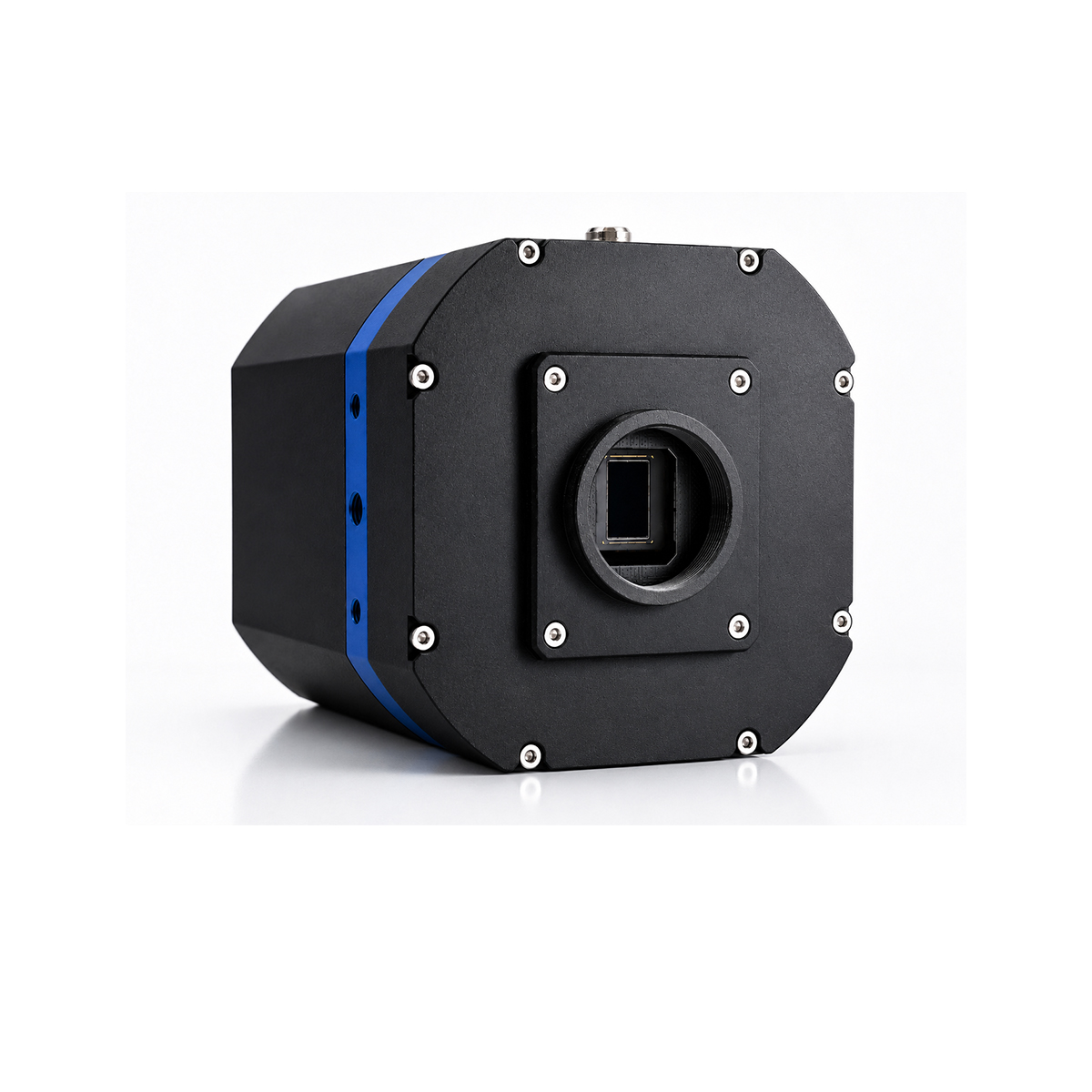
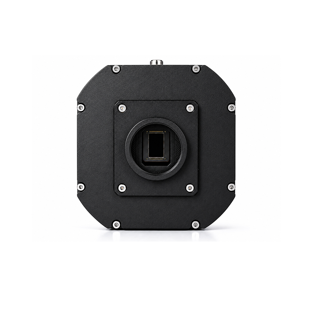
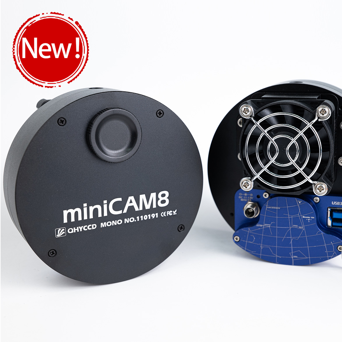
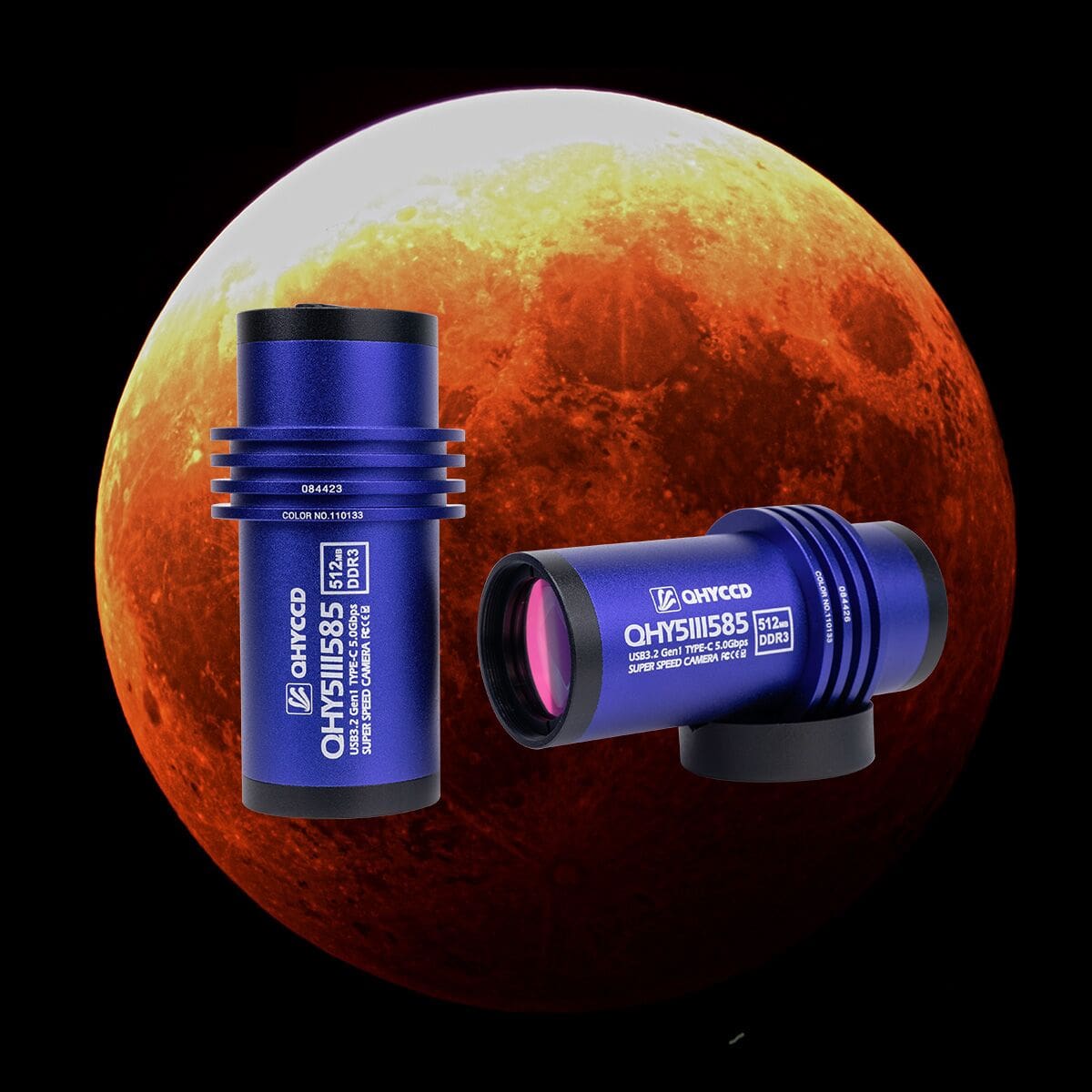
QHY585M is a high-performance monochrome cooled camera built around the Sony IMX585 back-illuminated CMOS sensor. It delivers outstanding imaging performance with high quantum efficiency, ultra-low read noise, exceptional near-infrared sensitivity, and a zero-amp glow design. Beyond astrophotography, the QHY585M is also well suited for a wide range of scientific and industrial applications, including scientific imaging, microscopy, spectroscopy, and near-infrared inspection.
Features
 High Near-Infrared Sensitivity

The IMX585 is a Sony Starvis II processor that enables high sensitivity and high dynamic range (HDR). It also improves sensitivity in the near-infrared range by approximately 1.7 times* compared to the IMX485. The new camera has a maximum quantum efficiency of 60% in the near-infrared band and 92% in the visible wavelength band.
*This data is officially provided by Sony: https://www.sony-semicon.com/cn/news/2021/2021062901.html

BSI
One benefit of the back-illuminated CMOS structure is improved full-well capacity. This is particularly helpful for sensors with small pixels. In a typical front-illuminated sensor, photons from the target entering the photosensitive layer of the sensor must first pass through the metal wiring that is embedded just above the photosensitive layer. The wiring structure reflects some of the photons and reduces the efficiency of the sensor.
In the back-illuminated sensor, the light is allowed to enter the photosensitive surface from the reverse side. In this case, the sensor’s embedded wiring structure is below the photosensitive layer. As a result, more incoming photons strike the photosensitive layer, and more electrons are generated and captured in the pixel well. This ratio of photon to electron production is called quantum efficiency. The higher the quantum efficiency, the more efficient the sensor is at converting photons to electrons, and hence the more sensitive the sensor is to capturing an image of something dim.
Zero Amplify Glow
QHY585M is also a zero-amplifier glow camera.

Anti-Dew Technology
Based on almost 20-year cooled camera design experience, the QHY cooled camera has implemented the fully dew control solutions. The optic window has a built-in dew heater, and the chamber is protected from internal humidity condensation. An electric heating board for the chamber window can prevent the formation of dew, and the sensor itself is kept dry with our silicon gel tube socket design for control of humidity within the sensor chamber.
 Cooling
In addition to dual-stage TE cooling, QHYCCD implements proprietary technology in hardware to control the dark current noise.
Linearity HDR Mode
 The native ADC of the IMX585 sensor is 12-bit. Compared to 16-bit, the 12-bit depth offers fewer bits, resulting in a relatively narrower dynamic range, which may lead to issues such as insufficient color gradation and potential information loss. During the product development of the QHY585 camera, QHYCCD merged high and low gain to extend the data to 16-bit. However, since this 16-bit depth is not native, a sudden shift in linearity might occur, affecting the smooth transition in images. To address this, QHYCCD developed the “Linearity HDR” mode, which uses an algorithm-based approach to correct image linearity through software, ensuring smoother transitions and richer color representation.
In the “Linearity HDR” mode, the full well is 46 ke⁻, while the read noise is only 1.0e⁻; the dynamic range reaches up to 46,300:1, equivalent to 93 dB or 15.5 stops.
Specification
| Model | QHY585M |
| CMOS Sensor | Sony IMX585 |
| Mono | Mono |
| BSI/FSI | BSI |
| Sensor Size | 1/1.2 inch |
| Pixel Size | 2.9μm*2.9μm |
| Total Pixel Area | 3856*2180 |
| Effective Pixels | 8 MP |
| Full Well Capacity | 54ke-
Linearity HDR Mode: 46ke- |
| Readout Noise | 0.76 – 7.8 e-
Linearity HDR Mode: 1.0e⁻ |
| Peak QE | M: 92% |
| Dynamic Range | Linearity HDR mode: The dynamic range reaches up to 46,300:1, equivalent to 93 dB or 15.5 stops. |
| A/D | Dual 12-bit (output as 16-bit) |
| Full Frame Rates | Full Resolution: 41.5FPS@8bit,23.5FPS @16bit |
| ROI Frame Rates | Full Resolution 1080Lines, 82FPS@8bit, 47FPS@16bit;640Lines, 177FPS@8bit, 105FPS@16bit |
| Exposure Time Range | 11μs-900sec |
| Shutter Type | Electronic Rolling Shutter |
| Built-in Image Buffer | 512MB DDR3 |
| Computer Interface | USB3.0 |
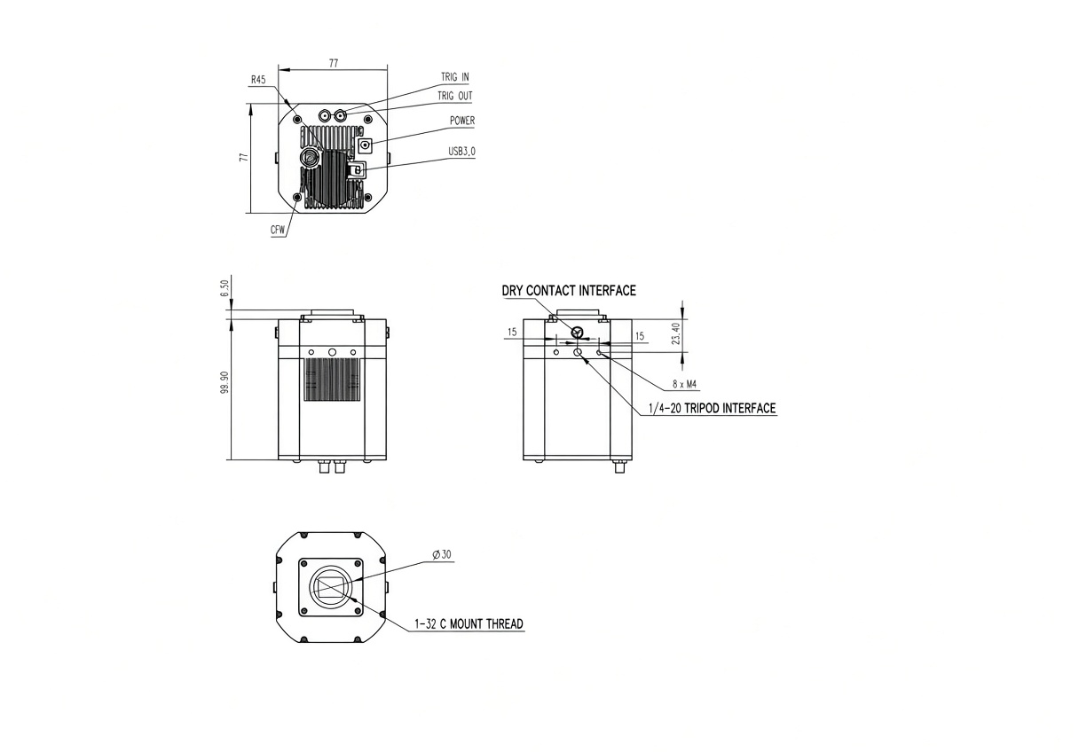
| Telescope Interface | C-mount lens |
| Optic Window Type | AR+AR |
| Filter Wheel | |
| Back Focal Length | |
| Cooling System | Dual Stage TEC cooler:
Long exposures (> 1 second) typically -45℃ below ambient |
| Weight |
Curves
Mechanical Dimensions
User Guide: HDR Correction of QHY585 Camera
FPGA version: 24-12-6 and its later version
SDK version: 24-12-26-12 and its later version
All-in-one version: 24.12.27.10 and its later version
HDR_correction will be on by default. (It is for 16-bit single frames and live, and not available for 8-bit.)
SharpCap version: 4.1.12311 and its later version
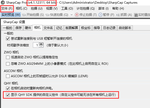
HDR Custom Control in SharpCap: “HDR_correction,” “HDR_L_K,” “HDR_L_b,” and “HDR_showKB”
HDR_L_K: stretch value of the low channel
HDR_L_b: offset value of the low channel
The two values influence the image linearity together.
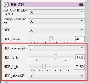 You can manually set values of “HDR_L_k” and “HDR_L_b” by yourself when switching off the “HDR_correction.” But in general we recommend switching it on. Improper values setting will cause issues like image banding.
HDR_showKB: On: values will be shown on the top left of the image; Off: no values shown
Note: In Linearity HDR mode, the Gain and Offset values are set by default and do not need to be adjusted. Any Gain and Offset settings in the software will have no effect.
User Guide: Start the Camera
Install “All-In-One” Driver&SDK Pack
Before Start: Input Voltage Requirements
The camera requires an input voltage between 11V and 13.8V. If the input voltage is too low the camera will stop functioning or it may reboot when the TEC power percent is high, causing a drain on the power. Therefore, please make sure the input voltage arrived to the camera is adequate. 12V is the best but please note that a 12V cable that is very long or a cable with small conductor wire may exhibit enough resistance to cause a voltage drop between the power supply and the camera. The formular is: V(drop) = I * R (cable). It is advised that a very long 12V power cable not be used. It is better to place the 12V AC adapter closer to the camera.
First connect the 12V power supply, then connect the camera to your computer via the USB3.0 cable. Make sure the camera is plugged in before connecting the camera to the computer, otherwise the camera will not be recognized. When you connect the camera for the first time, the system discovers the new device and looks for drivers for it. You can skip the online search step by clicking “Skip obtaining the driver software from Windows Update” and the computer will automatically find the driver locally and install it. If we take the 5IIISeries driver as an example (shown below), after the driver software is successfully installed, you will see QHY5IIISeries_IO in the device manager.
Please note that the input voltage cannot be lower than 11.5v, otherwise the device will be unable to work normally.
Install "All-In-One" System Pack
All-in-one Pack supports most QHYCCD models only except PoleMaster and several discontinued CCD cameras.
Download Page: https://www.qhyccd.com/download/
Video Tutorial: https://www.youtube.com/embed/mZDxIK0GZRc?start=1
- Since most of the contents of All-in-one package are plug-ins that support third-party software, the third-party capturing software that you want to use must be installed before the All-in-one package. Otherwise the program will report an error.
- ALL-IN-ONE Pack contains:
- System Driver, which is necessary for the camera operation and must be installed.
- WDM Broadcast Driver, which can provide a live signal to Obs and other live software, you can install it if you have such needs like opeing a live show.
- EZCAP_QT , which is developed by QHYCCD and can be used in QHY devices tests, and management of updates. So even if you won’t use EZCAP_QT for capturing, we suggest you install it.
- Ascom driver, which is necessary for the camera used in Ascom (the latest version of Ascom is 6.6).
- The two sorts of Ascom CFW Drivers correspond to two methods of controling the filter wheel: USB control and camera serial control. It is recommended that both drivers should be installed if you have a filter wheel.
- CP210X_VCP is a serial driver. Some computers come with the driver, but the computer without the driver may be failed of controling the filter wheel.
- SDKs for Third-party Software: Just pick and install the corresponding SDK according to the software you want to use. Don’t forget to check whether the software you are using is 32-bit or 64-bit and select the right SDKs.
- SHARPCAP is also included in the pack, you can choose 32-bit or 64-bit to install. This is authorized by SHARPCAP.
- QT LIB is a plug-in to ensure that 64-bit software can exeuate normally on some computers with poor compatibility.
- Difference between Stable version and Beta Version: Beta version is the latest version, which gives priority to support for the latest products (the stable version may not be compatible with those yet), and has some of the latest optimized ,but experimental features. The stable version is older than the beta version but more stable, so it is recommended for beginners who are not using the latest products.
- Don’t let the camera connect to the computer during the All-in-one pack installation process; connect it to the computer after all the installation is complete.
Connect DSO Imaging Software (e.g. NINA)
Before using software, make sure you have connected the cooling camera to the 12V power supply and connected it to the computer with a USB3.0 data cable. If it’s an uncooled camera, 12V power is not needed. We recommend 64-bit Software, like SharpCAP x64 , N.I.N.A x64. etc., especially when you’re using 16bit cameras.
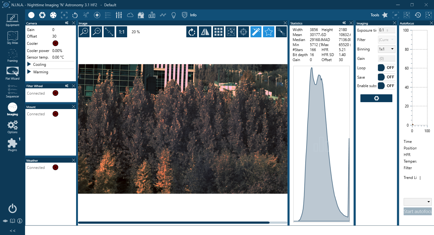
NINA supports direct connection via the QHY plugin as well as connection through the ASCOM driver. The following instructions assume a direct connection using the QHY plugin.
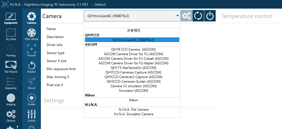
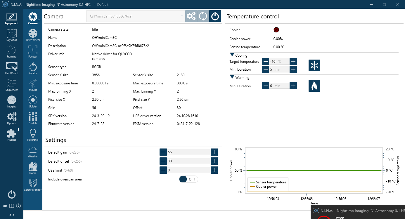
Set the Target temperature.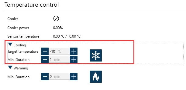
Set exposure time and start the shooting.
Connect Planetary Imaging Software (e.g. SharpCap)
The instructions below are based on SharpCap 3.1
- Launch SharpCap.
Click Camera in the menu bar and select your camera.
If the software and drivers mentioned above have been installed correctly, the image will appear automatically. And the frame rate can also be seen in the lower-left corner of the software window, as shown below.

- Main Interface Functions:
Capture Profiles
Preset management.
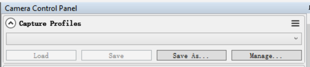
After SharpCap is restarted, the default settings are restored. If you frequently use one or more specific parameter configurations, you can adjust the parameters as needed and then click Save to store them as a preset. The preset can be directly recalled the next time you open the software.
Exposure
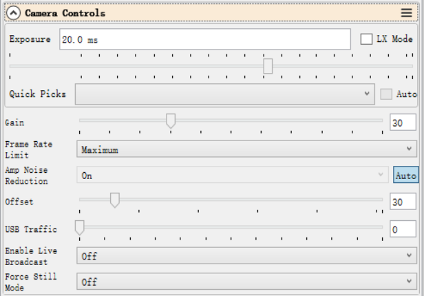
Sets the exposure duration. When LX Mode is enabled, the single-frame exposure time can be extended to longer values.
Gain
Equivalent to the ISO setting on a standard digital camera. Higher gain values result in higher sensitivity.
Frame Rate Limit
Limits the maximum frame rate. By default, no limit is applied. Users can set the limit manually if needed.
Offset
Adjusts the bias level. Even when the camera is completely covered, the image may not appear perfectly black. By adjusting the offset value, a more optimal dark frame can be achieved. The Histogram can be used to verify the adjustment.
USB Traffic
Controls the data transfer speed (frame rate). When set to 0, the camera operates at its maximum frame rate.
Enable Broadcast Mode
Enables the broadcast driver. For detailed usage instructions, please refer to the documentation available on the download page.
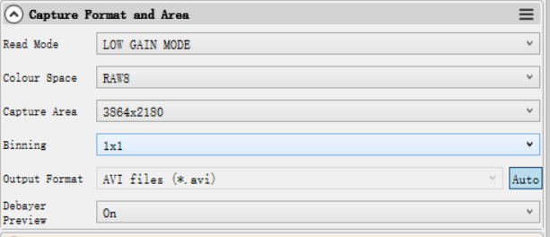
Read Mode
Some camera models support high-gain and low-gain readout modes.
Color Space
Select the output format.
Raw8 / Raw16 are 8-bit or 16-bit formats. Images and videos saved in Raw8 or Raw16 format will be monochrome, even when using a color sensor. Color information must be restored through debayering during post-processing.
RGB24 is a non-RAW format that outputs color images directly, but requires more storage space.
Capture Area
Select the resolution used for image capture.
Binning
Enable pixel binning for image capture.
Output Format
Select the output file format.
Debayer Preview
When this function is enabled, the live preview will be displayed in color even if a RAW format is selected. Please note that the saved images will still be monochrome.
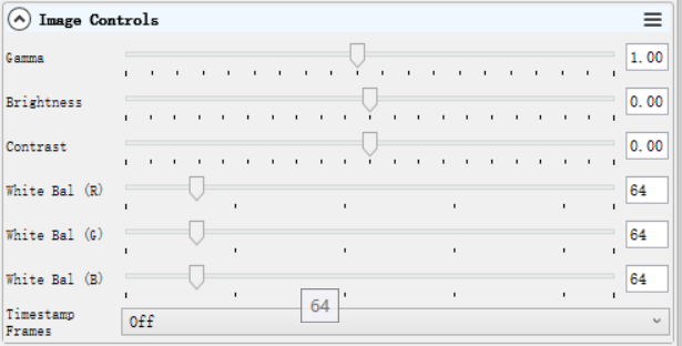
Gamma, Brightness, Contrast
Under normal operating conditions, we recommend leaving these settings unchanged.
White Balance (R/G/B)
This function is used for white balance calibration on color cameras. For detailed calibration instructions, please refer to the corresponding section on the color camera page.
This function is not required for monochrome cameras.
Histogram
The histogram is an important image reference tool. It can be used to check whether the white balance is set correctly, whether the offset value is appropriate, and whether the image is overexposed.
Its operating principle is the same as that of the histogram used in standard DSLR cameras.

Thermal Controls
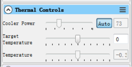
After the cooled camera is connected to a 12 V power supply, the temperature control circuit will be activated. You can control the CMOS sensor temperature by adjusting the settings shown below.
There are two main methods for temperature control:
Adjusting the cooler power
Setting a target temperature
If you wish to control the CMOS temperature by setting a target temperature, first click “Auto”, and then use the slider to set the desired target temperature.
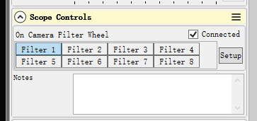
Scope Control: for filter wheel control
Select the corresponding filter wheel slot to control the rotation.
Note: The software must be started after the filter wheel has completed its rotation and returned to the home position; otherwise, the position will not be displayed correctly.
Using Ascom
QHY devices can operate with many software applications that support the ASCOM platform. MAXIM DL is used as an example below.
First, make sure that both the ASCOM platform and the QHY ASCOM driver have been successfully installed. Launch MAXIM DL and follow the instructions shown in the figure below to complete the setup.
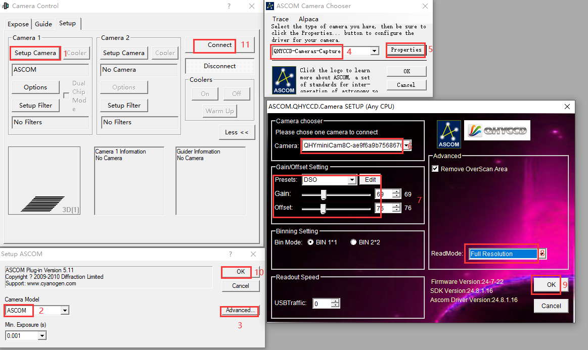
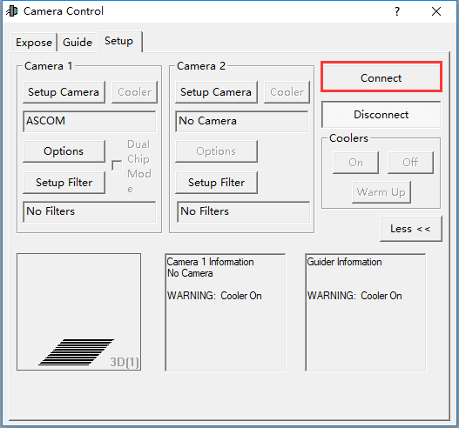
Click “Connect”
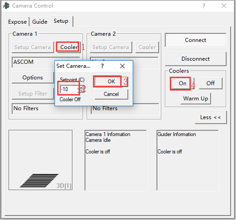
Set the cooling temperature.
Using EZCAP
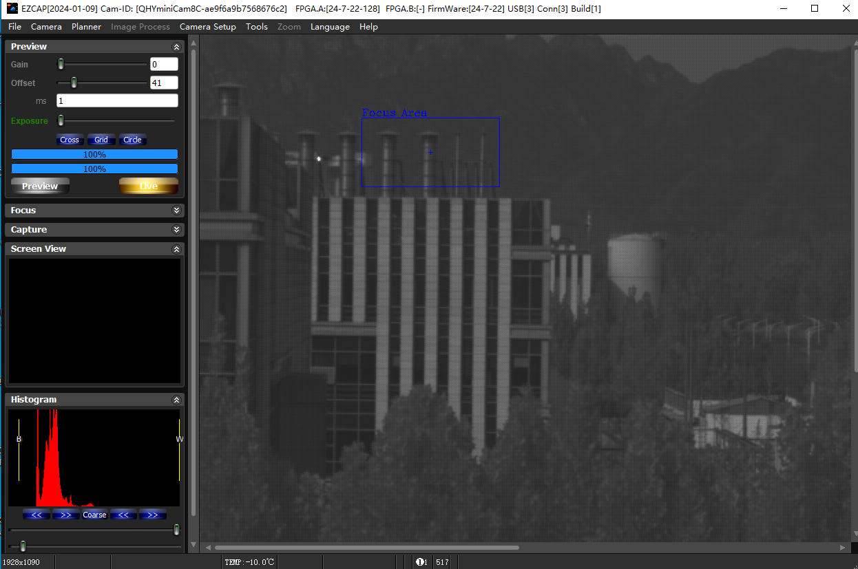
EZCAP_QT is software developed by QHYCCD. For QHYCCD cameras, it provides basic image capture functions.
Install the EZCAP_QT software and connect the camera to your computer using a USB 3.0 cable. Launch EZCAP_QT, then click “Connect” under Menu → Camera.
If the camera is successfully connected, the EZCAP_QT title bar will display the camera firmware version and camera ID, as shown in the figure below.

In Camera Setup, click Temp Control to set the CMOS sensor temperature.
You can enable Auto to define a target temperature. For example, here we set the target temperature to –10 °C. The CMOS sensor temperature will quickly drop to the target value, typically within 2–3 minutes.
To disable cooling, select Stop. If you prefer to control the cooling power without setting a target temperature, you can manually set the cooling power as a percentage.
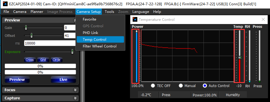
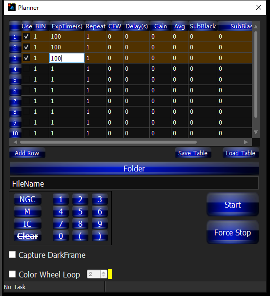
In EZCAP_QT, there is an Image Task Planner for sequence imaging.
Check Use to enable the task.
Set the following parameters:
Bin
ExpTime – exposure time
Repeat – number of frames
CFW – filter wheel position
Gain – gain value for the sequence
Click Folder to set the save path. (It is recommended to avoid special characters in the path and use English letters.)
Click Start to begin the sequence capture, and Force Stop to close the current task.
User Guide: Camera Maintenance
Drying the camera CMOS chamber
On the side of the front end of the camera, there is a drying port designed for use with a drying tube to dehumidify the CMOS sealed chamber. If moisture inside the CMOS chamber causes the sensor glass to fog up, you can connect a drying tube to this port for drying. Place effective silica gel desiccant in the drying tube and ensure it contains cotton to prevent dust particles from entering the CMOS chamber. Please refer to the connection instructions below.
Notes:
Turn off cooling before starting the drying process.
FAQ
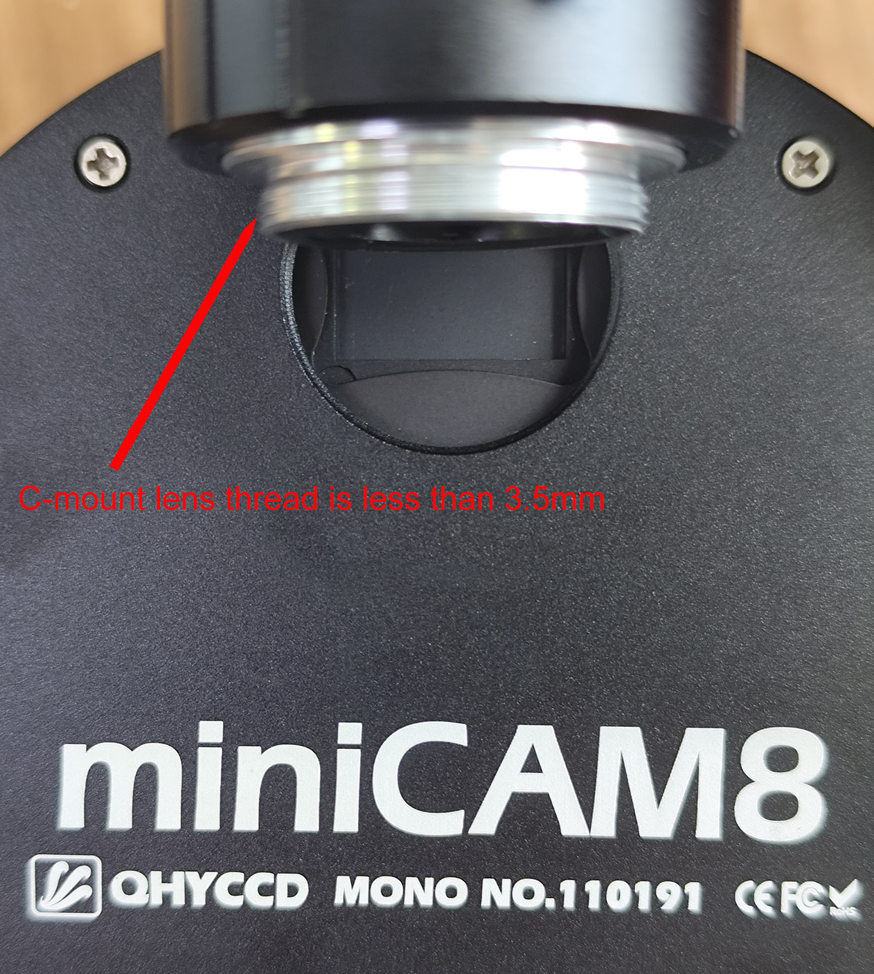
Notes on C-mount lens connection
The camera back focus is 17.5mm, which theoretically supports C-mount lenses. However, the thread length of the C-mount lens connected to the camera must be less than 3.5mm, otherwise the camera filter wheel will be stuck and the wheel will not rotate.